Tachometer malfunction
DESCRIPTION
In this circuit, the combination meter assembly receives engine speed signals from the ECM via CAN communication. The combination meter assembly displays the engine speed calculated based on the data received from the ECM.
WIRING DIAGRAM
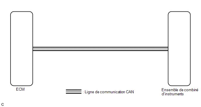
PRECAUTION / NOTICE / HINT
NOTICE:
- Before replacing the ECM, refer to the Registration section.
- with Smart Key System:
Click here

- without Smart Key System:
Click here
- with Smart Key System:
- When replacing the instrument cluster assembly, always use a new part. If an instrument cluster assembly that was installed in another vehicle is used, the stored information will not match the information transmitted by the vehicle, and a DTC may be stored.
PROCEDURE
INSPECT DTCs (METER/GAUGE SYSTEM)
(a) Check that the meter/gauge system DTCs are output.
Click here
Result:
Result | Proceed to |
|---|---|
The meter/gauge system DTCs are not output. |
A |
The meter/gauge system DTCs are output. |
B |
| B |  |
GO TO DIAGNOSTIC TROUBLE CODE CHART |
|

INSPECT DTCs (SFI SYSTEM)
(a) Check whether DTCs related to the SFI system are output.
- with fuel vapor absorber pump module:
Click here
- without fuel vapor absorber pump module:
Click here
Result:
Result | Proceed to |
|---|---|
No SFI system DTCs are output. |
A |
SFI system DTCs are output. |
B |
| B | |
GO TO DIAGNOSTIC TROUBLE CODE CHART |
|
PERFORM ACTIVE TEST USING TECHSTREAM (ENGINE SPEED, ENGINE RPM)
(a) Connect the Techstream to the DLC3.
(b) Turn the ignition switch to ON.
(c) Turn on the Techstream.
(d) Select the following menus:
(1) For engine: Powertrain / Engine and ECT / Data List.
(2) For combination meter: Body Electrical / Combination Meter / Data List.
(e) Read the Data List by following the instructions on the Techstream.
(1) Engine and ECT
Powertrain > Engine and ECT > Data ListTester display | Item | Range | Normal Condition | Diagnostic Note |
|---|---|---|---|---|
Engine Speed |
Engine speed |
Min.: 0 rpm, Max.: 16,383 rpm |
710 to 810 rpm: At idle, engine warm |
If the crankshaft position sensor malfunctions, "Engine Speed" is approximately 0 rpm or fluctuates significantly from the actual engine speed |
Engine Speed
(2) Combination meter.
Body Electrical > Combination Meter > Data ListTester display | Item | Range | Normal Condition | Diagnostic Note |
|---|---|---|---|---|
Engine Rpm |
Engine speed |
Min.: 0 rpm, Max.: 12,750 rpm |
Almost the same as the tachometer |
- |
Engine Rpm
Result:
Result | Proceed to |
|---|---|
The ECU Data List values do not match. |
A |
The ECU Data List values match. |
B |
HINT:
- If the ECU Data List values match, an internal malfunction of the ECM is likely.
- If the ECU Data List values do not match, an ECM output signal error or an internal malfunction of the combination meter assembly is likely.
| A | |
REPLACE ECM |
| B | |
REPLACE COMBINATION METER ASSEMBLY |