Fuel gauge display malfunction
DESCRIPTION
OPERATION
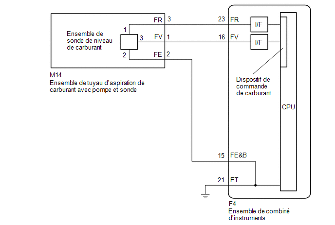
The combination meter assembly uses the fuel injection volume signal sent from the ECM and the fuel level sensor assembly to detect the amount of fuel remaining in the fuel tank assembly. Each gauge assembly has a variable resistor whose resistance changes according to the amount of fuel remaining. The gauge assemblies receive voltage from the combination meter assembly and change the voltage according to this resistance, which varies with the amount of fuel remaining in the fuel tank assembly. The combination meter assembly receives the fuel injection volume signal from the ECM, detects the voltage between each resistor and each variable resistor in the combination meter assembly, and operates the fuel gauge.
FUEL GAUGE READING
(a) During normal driving:
Because the fuel level in the fuel tank assembly changes when driving on inclines or when braking, the fuel gauge is updated based on the fuel injection volume value during normal driving. However, because the fuel injection volume has a margin of error, the value is displayed after correction using input values from the fuel level sensor assembly.
(b) When refueling:
The fuel level in the fuel tank rises quickly when fuel is added. If the averaging process used during normal driving were applied in this case, the fuel gauge value could not be updated quickly. Therefore, when it is determined that fuel has been added to the vehicle based on the shift lever position and changes in the fuel level, the output values of the fuel level sensor assembly are immediately reflected in the fuel gauge value. This control is called the refill limit.
FUEL FILL LIMIT CONDITIONS
NOTICE:
Refuel with the ignition switch in the OFF position for safety and to establish the fill limit so that an appropriate fuel gauge reading is obtained. If it is necessary to add fuel with the ignition switch in the ON position, place the shift lever in the P or N position.
(a) Normal result of state estimation (when normal filling is used for refueling)
With the ignition switch in the OFF position, the fuel level sensor assembly detects a change in fuel level of at least 5.0 liters (5.3 US qt, 4.4 Imp. qt).
(b) Other limit conditions (when using other means for refueling)
One of the following conditions is met
- With the vehicle and engine stopped and the ignition switch in the ON position, the fuel level sensor assembly detects a change in fuel level of at least 5.0 liters (5.3 US qt, 4.4 Imp. qt).
- With the vehicle stopped, the engine running, the ignition switch in the ON position and the shift lever in P or N, the fuel level sensor assembly detects a change in fuel level of at least 5.0 liters (5.3 US qt, 4.4 Imp. qt).
- With the vehicle stopped, the engine running, the ignition switch in the ON position and the shift lever in a driving position, the fuel level sensor assembly detects a change in fuel level of at least 15.0 liters (15.9 US qt, 13.2 Imp. qt).
PRECAUTIONS TO TAKE WHEN REFUELING
The fuel level sensor assembly cannot detect fuel level changes in certain areas (around points E and F). Therefore, even if at least 5.0 liters (5.3 US qt, 4.4 Imp. qt) of fuel is added, the refueling evaluation may not be completed, and the fuel gauge reading may not change when the fuel level is within such ranges.
FORCED RESET OF THE FUEL GAUGE
When the vehicle is driven at or above 1.8 km/h, if the output values of the fuel level sensor assembly differ from the fuel gauge value by at least 15.0 liters (15.9 US qt, 13.2 Imp. qt) for approximately 2 minutes, the output values of both sensor assemblies are immediately reflected in the fuel gauge value to correct the reading when the refill evaluation cannot be completed.
WIRING DIAGRAM
PRECAUTION / NOTICE / HINT
NOTICE:
When replacing the instrument cluster assembly, always use a new part. If an instrument cluster assembly that was installed in another vehicle is used, the stored information will not match the information transmitted by the vehicle, and a DTC may be stored.
HINT:
The fuel level warning light illuminates when the fuel level is below 9.96 liters (10.5 US qt, 8.8 Imp. qt).
PROCEDURE
CHECK SYMPTOMS
(a) Ask the customer to describe the symptoms of the problem.
Result:
Result | Proceed to |
|---|---|
The malfunction occurs during refueling (even after adding fuel, the value does not increase at all or increases very slowly, etc.) |
A |
The malfunction occurs during normal driving (the value does not change, decreases rapidly, or decreases when the vehicle is not being driven, etc.) (the symptom reproduces) |
B |
The malfunction occurs during normal driving (the value does not change, decreases rapidly, or decreases when the vehicle is not being driven, etc.) (the symptom does not reproduce) |
C |
| B |  |
GO TO STEP 10 |
| C | |
GO TO STEP 14 |
|

CHECK WHETHER DTCs ARE OUTPUT
(a) Check whether DTCs related to the SFI system are output.
- with fuel vapor absorber pump module:
Click here

- without fuel vapor absorber pump module:
Click here
Result:
Result | Proceed to |
|---|---|
No SFI system DTCs are output. |
A |
SFI system DTCs are output. (Without fuel vapor absorber pump module) |
B |
SFI system DTCs are output. (With fuel vapor absorber pump module) |
C |
| B | |
GO TO SFI SYSTEM |
| C | |
GO TO SFI SYSTEM |
|
CHECK WHETHER DTCs ARE OUTPUT
(a) Check whether the vehicle stability control system DTCs are output.
Click here
Result:
Result | Proceed to |
|---|---|
DTCs related to the vehicle stability control system are not output. |
A |
DTCs related to the vehicle stability control system are output. |
B |
| B | |
GO TO VEHICLE STABILITY CONTROL SYSTEM |
|
CHECK FUEL GAUGE OPERATION BY ADDING FUEL
(a) Record the fuel gauge value.
(b) If the fuel tank assembly is nearly full, drain at least 20 liters of fuel. (Not necessary if the fuel tank assembly is only partially filled.)
(c) Disconnect the negative (-) battery terminal cable to reset the fuel gauge.
HINT:
Make sure the ignition switch is in the OFF position before disconnecting the negative (-) battery terminal cable.
(d) Connect the cable to the negative (-) battery terminal and set the engine switch to the ON position.
(e) Check that the fuel gauge has been reset.
(f) Drive the vehicle at a speed of at least 1.8 km/h, then place the shift lever in the P position and set the power switch to the OFF position.
(g) Add at least 5.0 liters of fuel, set the power switch to the ON position, and check that the fuel gauge value increases in proportion to the amount of fuel added.
Result:
Result | Proceed to |
|---|---|
The fuel gauge value increases in proportion to the amount of fuel added |
A |
The fuel gauge value does not change, even when fuel is added |
B |
| B | |
GO TO STEP 6 |
|
CHECK FUEL TANK ASSEMBLY
HINT:
Check whether the fuel tank assembly is deformed, whether there are foreign objects, or whether the fuel level sensor is improperly installed, as these could cause the fuel gauge to malfunction.
(a) Visually check the fuel tank assembly for any abnormalities.
(b) Check whether there is an excessive amount of foreign objects in the fuel tank assembly.
(c) Check the installation condition of the fuel tank assembly and the fuel level sensor assembly.
Result:
Result | Proceed to |
|---|---|
Normal |
A |
The fuel tank assembly does not function normally. (without fuel vapor absorber pump module) |
B |
The fuel tank assembly does not function normally. (with fuel vapor absorber pump module) |
C |
There is an excessive amount of foreign objects in the fuel tank assembly. |
D |
The fuel tank assembly and the fuel level sensor assembly are not installed correctly. |
E |
| B | |
REPLACE FUEL TANK ASSEMBLY |
| C | |
REPLACE FUEL TANK ASSEMBLY |
| D | |
CLEAN INSIDE OF FUEL TANK ASSEMBLY |
| E | |
REINSTALL FUEL TANK ASSEMBLY OR FUEL LEVEL SENSOR ASSEMBLY CORRECTLY |
|
READ VALUE USING TECHSTREAM (FUEL INPUT)
(a) Connect the Techstream to the DLC3.
(b) Turn the ignition switch to ON.
(c) Turn on the Techstream.
(d) Select the following menus: Body Electrical / Combination Meter / Data List.
(e) Read the Data List by following the instructions on the Techstream.
Body Electrical > Combination Meter > Data ListTester display | Item | Range | Normal Condition | Diagnostic Note |
|---|---|---|---|---|
Fuel Input |
Fuel Input |
Min.: 0 L, Max.: 127.5 L |
|
Unit: liter |
Fuel Input
Result:
Result | Proceed to |
|---|---|
The fuel level data displayed on the Techstream is almost identical to the fuel gauge indication. |
A |
The fuel level data displayed on the Techstream differs from the fuel gauge indication. |
B |
| B | |
REPLACE COMBINATION METER ASSEMBLY |
|
CHECK WIRE HARNESS AND CONNECTOR (INSTRUMENT CLUSTER - FUEL SUCTION TUBE WITH PUMP AND GAUGE ASSEMBLY)
(a) Disconnect the connector from the combination meter assembly F4.
(b) Disconnect connector M14 of the fuel suction tube with pump and gauge assembly.
(c) Measure the resistance according to the value(s) in the table below.
Standard resistance:
Tester Connection | Condition | Specified Condition |
|---|---|---|
M14-1 (FV) - F4-16 (FV) |
Always |
Below 1 Ω |
M14-2 (FE) - F4-15 (FE&B) |
Always |
Below 1 Ω |
M14-3 (FR) - F4-23 (FR) |
Always |
Below 1 Ω |
M14-1 (FV) - Body ground |
Always |
10 kΩ minimum |
M14-2 (FE) - Body ground |
Always |
10 kΩ minimum |
M14-3 (FR) - Body ground |
Always |
10 kΩ minimum |
| NG | |
REPAIR OR REPLACE HARNESS OR CONNECTOR |
|
INSPECT FUEL SUCTION TUBE WITH PUMP AND GAUGE ASSY
(a) Remove the fuel suction tube with pump and gauge assembly.
- with fuel vapor pump module: Click here
- without fuel vapor pump module: Click here
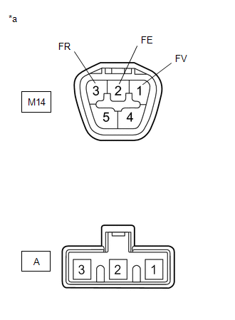
(b) Measure the resistance according to the value(s) in the table below. Standard resistance:
|
|
| NG | |
REPLACE FUEL SUCTION TUBE WITH PUMP AND GAUGE ASSY |
|
INSPECT FUEL LEVEL SENSOR ASSY
(a) Remove the fuel level sensor assy.
Click here
(b) Inspect the fuel level sensor assy.
Click here
| OK | |
REPLACE COMBINATION METER ASSEMBLY |
| NG | |
REPLACE FUEL LEVEL SENSOR ASSY |
CHECK WHETHER DTCs ARE OUTPUT
(a) Check whether DTCs related to the SFI system are output.
- with fuel vapor absorber pump module:
Click here
- without fuel vapor absorber pump module:
Click here
Result:
Result | Proceed to |
|---|---|
No SFI system DTCs are output. |
A |
SFI system DTCs are output. (Without fuel vapor absorber pump module) |
B |
SFI system DTCs are output. (With fuel vapor absorber pump module) |
C |
| B | |
GO TO SFI SYSTEM |
| C | |
GO TO SFI SYSTEM |
|
CHECK WHETHER DTCs ARE OUTPUT
(a) Check whether the vehicle stability control system DTCs are output.
Click here
Result:
Result | Proceed to |
|---|---|
DTCs related to the vehicle stability control system are not output. |
A |
DTCs related to the vehicle stability control system are output. |
B |
| B | |
GO TO VEHICLE STABILITY CONTROL SYSTEM |
|
CHECK WHETHER DTCs ARE OUTPUT
(a) Check the DTCs.
Click here
Result:
Result | Proceed to |
|---|---|
No DTCs are output. |
A |
DTCs are output. |
B |
| B | |
GO TO DTC B1500 |
|
CHECK FUEL GAUGE
(a) Disconnect the negative (-) battery terminal cable to reset the fuel gauge.
HINT:
Make sure the ignition switch is in the OFF position before disconnecting the negative (-) battery terminal cable.
(b) Connect the cable to the negative (-) battery terminal and set the engine switch to the ON position.
(c) Check whether the fuel gauge value matches the amount of fuel remaining in the fuel tank assembly.
Result:
Result | Proceed to |
|---|---|
The fuel gauge value matches the amount of fuel remaining in the fuel tank assembly. |
A |
The fuel gauge value does not match the amount of fuel remaining in the fuel tank assembly. |
B |
| A | |
END |
| B | |
GO TO STEP 6 |
CHECK WHETHER DTCs ARE OUTPUT
(a) Check whether any DTCs related to the SFI system are output. (for 3ZR-FAE)
- with fuel vapor absorber pump module:
Click here
- without fuel vapor absorber pump module:
Click here
Result:
Result | Proceed to |
|---|---|
No SFI system DTCs are output. |
A |
SFI system DTCs are output. (Without fuel vapor absorber pump module) |
B |
SFI system DTCs are output. (With fuel vapor absorber pump module) |
C |
| B | |
GO TO SFI SYSTEM |
| C | |
GO TO SFI SYSTEM |
|
CHECK WHETHER DTCs ARE OUTPUT
(a) Check whether the vehicle stability control system DTCs are output.
Click here
Result:
Result | Proceed to |
|---|---|
DTCs related to the vehicle stability control system are not output. |
A |
DTCs related to the vehicle stability control system are output. |
B |
| B | |
GO TO VEHICLE STABILITY CONTROL SYSTEM |
|
CHECK FUEL TANK ASSEMBLY
HINT:
Check whether the fuel tank assembly is deformed, whether there are foreign objects, or whether the fuel level sensor is improperly installed, as these could cause the fuel gauge to malfunction.
(a) Visually check the fuel tank assembly for any abnormalities.
(b) Check whether there is an excessive amount of foreign objects in the fuel tank assembly.
(c) Check the installation condition of the fuel tank assembly and the fuel level sensor assembly.
Result:
Result | Proceed to |
|---|---|
Normal |
A |
The fuel tank assembly does not function normally. (without fuel vapor absorber pump module) |
B |
The fuel tank assembly does not function normally. (with fuel vapor absorber pump module) |
C |
There is an excessive amount of foreign objects in the fuel tank assembly. |
D |
The fuel tank assembly and the fuel level sensor assembly are not installed correctly. |
E |
| A | |
REPLACE COMBINATION METER ASSEMBLY |
| B | |
REPLACE FUEL TANK ASSEMBLY |
| C | |
REPLACE FUEL TANK ASSEMBLY |
| D | |
CLEAN INSIDE OF FUEL TANK ASSEMBLY |
| E | |
REINSTALL FUEL TANK ASSEMBLY OR FUEL LEVEL SENSOR ASSEMBLY CORRECTLY |