Meter illumination remains dark
DESCRIPTION
The meter assembly receives signals from this circuit to control the meter illumination. The meter assembly adjusts the illumination level according to the user's operation of the illumination control dimmer switch.
WIRING DIAGRAM
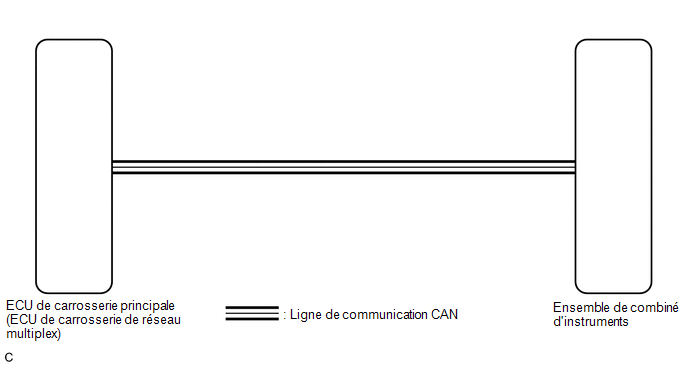
PRECAUTION / NOTICE / HINT
NOTICE:
- Before replacing the main body ECU (multiplex network body ECU), refer to the registration section.*1
Click here

- When replacing the instrument cluster assembly, always use a new part. If an instrument cluster assembly that was installed in another vehicle is used, the stored information will not match the information transmitted by the vehicle, and a DTC may be stored.
- *1: with Smart Key System
HINT:
- The meter illumination dims when the tail lights are on.
- Setting the meter illumination level to maximum brightness cancels the meter illumination dimming described above.
- Setting the meter illumination level to minimum brightness turns off the meter illumination.
- The sensitivity of the auto light control sensor can be customized.
Click here
PROCEDURE
INSPECT CAN COMMUNICATION SYSTEM
(a) Check whether CAN communication system DTCs are output.
Click here
Result:
Result | Proceed to |
|---|---|
CAN communication DTCs are not output. |
A |
CAN communication DTCs are output. |
B |
| B |  |
GO TO CAN COMMUNICATION SYSTEM |
|

CHECK WHETHER DTCs ARE OUTPUT
(a) Check whether any lighting system DTCs are output.
Click here
Result:
Result | Proceed to |
|---|---|
DTC B1244 is not output. |
A |
DTC B1244 is output. |
B |
| B | |
GO TO DTC B1244 |
|
REPLACE COMBINATION METER ASSEMBLY
(a) Replace the combination meter assembly.
Click here
OK:
The meter assembly operates normally again.
| OK | |
END |
| NG | |
REPLACE MAIN BODY ECU (MULTIPLEX NETWORK BODY ECU) |