Speedometer malfunction
DESCRIPTION
The combination meter assembly receives vehicle speed signals from the skid control ECU (brake actuator assembly) via CAN communication. The speed sensor detects wheel rotation speed and sends the corresponding signals to the skid control ECU (brake actuator assembly). The skid control ECU (brake actuator assembly) supplies power to the vehicle speed sensor. The skid control ECU (brake actuator assembly) detects vehicle speed signals based on voltage pulses.
HINT:
- Tire size, tire pressure and tire wear are among the factors affecting the indicated vehicle speed. The speedometer reading has a permissible margin of error. This can be checked using the Techstream. For details on the test and the margin of error, refer to the reference table.
Click here

- If the vehicle speed sensor circuit malfunctions, the skid control ECU (brake actuator assembly) stores DTCs. Perform troubleshooting for the vehicle stability control system.
Click here
WIRING DIAGRAM
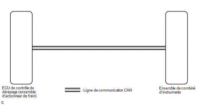
PRECAUTION / NOTICE / HINT
NOTICE:
- If the vehicle speed is outside the permissible range after testing, perform the check on the vehicle.
Click here
- When replacing the instrument cluster assembly, always use a new part. If an instrument cluster assembly that was installed in another vehicle is used, the stored information will not match the information transmitted by the vehicle, and a DTC may be stored.
HINT:
Before starting the following check, check the tire size and tire pressure.
PROCEDURE
INSPECT DTCs (METER/GAUGE SYSTEM)
(a) Check that the meter/gauge system DTCs are output.
Click here
Result:
Result | Proceed to |
|---|---|
The meter/gauge system DTCs are not output. |
A |
The meter/gauge system DTCs are output. |
B |
| B |  |
GO TO DIAGNOSTIC TROUBLE CODE CHART |
|

CHECK DTCs (VEHICLE STABILITY CONTROL SYSTEM)
(a) Check whether the vehicle stability control system DTCs are output.
Click here
Result:
Result | Proceed to |
|---|---|
DTCs related to the vehicle stability control system are not output. |
A |
DTCs related to the vehicle stability control system are output. |
B |
| B | |
GO TO DIAGNOSTIC TROUBLE CODE CHART |
|
PERFORM ACTIVE TEST USING TECHSTREAM (SPEED METER OPERATION)
(a) Connect the Techstream to the DLC3.
(b) Turn the ignition switch to ON.
(c) Turn on the Techstream.
(d) Select the following menu items: Body Electrical / Combination Meter / Active Test.
(e) Perform the Active Test by following the Techstream instructions.
Body Electrical > Combination Meter > Active TestTester display | Item | Control Range | Diagnostic Note |
|---|---|---|---|
Speed Meter Operation |
Speedometer |
OFF, 0, 40, 80, 120, 160, 200, 240, 280 |
There is a discrepancy between the value shown on the speedometer (control range → speedometer display) (1) For analog speedometer*1 Reference km/h:
|
- *1: with occupant classification system
- *2: with occupant classification system and without daytime running light cancel function
- *3: with occupant classification system and with daytime running light cancel function
Speed Meter Operation
OK:
The speedometer indication is normal.
| OK | |
REPLACE SKID CONTROL ECU (BRAKE ACTUATOR ASSEMBLY) |
| NG | |
REPLACE COMBINATION METER ASSEMBLY |