Oxygen Sensor
Vehicles are equipped with either one oxygen sensor or two oxygen sensors. In a two-sensor system, the primary oxygen sensor is installed upstream of the catalytic converter and monitors the oxygen content of the exhaust gases leaving the engine. The secondary oxygen sensor monitors the oxygen content of the exhaust gases downstream of the catalytic converter. The oxygen sensor responds to the oxygen content in the exhaust gases and generates an output voltage fluctuating from 0.1 V (high oxygen content, lean mixture) to 0.9 V (low oxygen content, rich mixture).
Site preparation for construction of a heated hangar.The changing output voltage from the sensors is sent to the electronic control unit, which determines the oxygen-to-fuel ratio in the air-fuel mixture.
The control unit regulates the air/fuel ratio in the mixture by controlling the injector open time. At an air-fuel ratio of 14.7 parts air to 1 part fuel, the content of harmful substances in the exhaust gases is minimal, and at this ratio the catalytic converter cleans the gases with maximum efficiency.
The electronic control unit together with the oxygen sensor maintains the air-fuel mixture composition precisely at the specified level.
If the oxygen sensor temperature is below its normal operating temperature, i.e. below 300 °C, no voltage will be present at the sensor. Therefore, until the engine warms up, no signal from the oxygen sensor is received by the electronic control unit, and the unit operates in open-loop mode.
If, after the engine has warmed up or after at least 2 minutes of engine operation, the primary oxygen sensor consistently produces a voltage not exceeding 0.7 V at an engine speed of 1500 rpm, the electronic control unit will set code 21. Code 27 indicates a fault in the secondary oxygen sensor.
If the sensor or its circuit is faulty, the electronic control unit operates in open-loop mode, i.e. the unit meters fuel according to the value programmed at its input, rather than according to the oxygen sensor signal.
Correct sensor operation depends on four conditions:
– Electrical: the low voltage generated by the sensor is very sensitive to the condition of the wire connections, which must always be clean and secure and must be checked first, both when diagnostic trouble codes are present and when a sensor fault is suspected;
– Outside air supply: the sensor is designed so that air circulates through its internal space. Each time the sensor is removed or installed, make sure the sensor air passages are clean;
– Operating temperature: the sensor signal is not sent to the electronic control unit until the sensor temperature reaches approximately 300 °C (take this factor into account when evaluating sensor operation);
– Use of unleaded gasoline is an essential condition for correct sensor operation.
In addition to the above conditions, observe the following special precautions when servicing the sensor:
– The oxygen sensor lead wire and connector are non-separable and are not disconnected from the sensor;
– Damage or separation of the lead wire or connector may adversely affect sensor operation;
– Do not allow dirt, lubricants, or other foreign materials to contact the connector or the sensor ceramic insulator;
– Do not clean the sensor with any type of cleaning agent;
– Do not drop the sensor or handle it roughly;
– Make sure the sensor silicone boot is installed correctly to prevent the boot from melting, which may cause sensor failure.
Inspection
PROCEDURE
1. To check the sensor, connect a digital voltmeter and monitor the reading with the engine running (the voltmeter should show a voltage in the fractions-of-a-volt range). To do this, locate the oxygen sensor connector and insert the voltmeter probe into the black wire contact from the rear of the sensor connector.
2. To make a proper connection to the wire, fit a long straight pin probe onto the wire and push the probe along the wire into the connector until it contacts the metal terminal of the wire. Connect the positive voltmeter lead to the probe and the negative lead to ground.
3. Start the engine and monitor the voltage from the main oxygen sensor during warm-up (the voltage should be in the fractions-of-a-volt range). The oxygen sensor will continuously generate a voltage signal, which with a cold engine (open loop) is 0.1–0.2 volts. After approximately 2 minutes the engine will warm up to operating temperature and the oxygen sensor voltage will fluctuate between 0.1 and 0.9 volts (closed-loop engine control is activated). If the oxygen sensor signal differs from these values, replace the sensor.
4. To access the connector of the auxiliary oxygen sensor, remove the front passenger seat.
5. To check the auxiliary oxygen sensor, locate the connector and perform the same test procedures as for the main oxygen sensor.
6. Check the auxiliary oxygen sensor heater (if equipped) as follows. Disconnect the oxygen sensor connector and connect an ohmmeter between terminals +B and HT in the connector on the sensor side. The ohmmeter reading should be within 11.0–17.0 ohms.
* Only some vehicles are equipped with a heated oxygen sensor. The heated oxygen sensor connector has four terminals.
7. Check the voltage supply to the oxygen sensor heater. With the ignition on (engine not running), check for battery voltage between the black/red (positive +) and black/blue (negative –) wires at the harness-side connector.

8. On 1993–1994 models, the oxygen sensor can be checked by another method. With the engine fully warmed up and the oxygen sensor connected, connect the positive voltmeter lead to terminal VF1 of the diagnostic connector (indicated by the arrow) and the negative lead to terminal E1. Raise the engine speed to 2500 rpm, then connect terminals TE1 and E1 of the diagnostic connector with a jumper wire or a paper clip.
* Measure the voltage only with a moving-needle (analog) voltmeter, as it is necessary to observe the needle fluctuations.
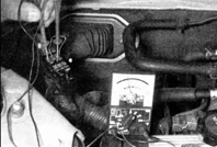
9. Hold the engine at 2500 rpm for approximately 2 minutes, then connect terminals TE1 and E1 of the diagnostic connector. Count the number of needle deflections in 10 seconds. The number of needle deflections must be at least 8. If the number of deflections is less, warm up the engine again and repeat the check.
10. If the number of needle deflections is still less than 8, remove the jumper connecting terminals TE1 and E1. While maintaining the engine speed at 2500 rpm, measure the voltage between terminals VF1 and E1. If the voltage is greater than 0 V, replace the oxygen sensor. If the voltage is 0, read the diagnostic trouble codes (see subsection 6.4.1) and determine the cause of the malfunction.
11. If codes 21, 25 or 26 are obtained, disconnect the positive crankcase ventilation (PCV) hose from the cylinder head cover (see subsection 6.8) and measure the voltage between VF1 and E1. If the voltage is 0, replace the sensor. If the measured voltage is greater than 0 V, the engine is running with a rich mixture and the fuel system requires repair.
12. If other codes are obtained, repair the specific sensor or circuit.
Replacement
* When cooled, the exhaust manifold or exhaust pipe into which the sensor is threaded contracts, so the sensor is difficult to remove from a cold engine. To avoid damaging the sensor (if it will be reused), start the engine and let it warm up for 1–2 minutes, then stop the engine. Be careful not to burn yourself while performing the following steps.
PROCEDURE
1. Disconnect the battery negative cable.
2. Raise the vehicle and support it on jack stands.
3. Carefully disconnect the sensor wiring connector.

4. Unscrew the oxygen sensor from the exhaust pipe (the photo shows a special extended socket that makes sensor removal easier).
* To avoid stripping the sensor threads, do not apply excessive force when unscrewing the sensor.
The oxygen sensor may be threaded into the exhaust manifold or secured with two bolts.
5. Apply anti-seize compound to the threads to make future sensor removal easier. Anti-seize compound is always applied to the threads of new sensors. When a used sensor is removed and reinstalled, reapply anti-seize compound.
6. Tighten the sensor securely.
7. Connect the sensor wiring connector to the engine wiring harness.
8. Lower the vehicle and connect the battery negative cable.
Test yourself
A quick Toyota Corolla quiz: every answer comes with an explanation and a link to the manual page.