Exhaust Gas Recirculation (EGR) System
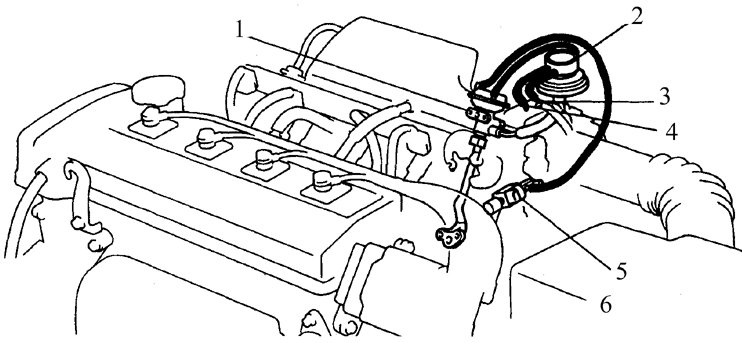
EGR System Components
1. EGR valve
2. Vacuum switching valve (VSV)
3. R port
4. E port
5. Vacuum modulator
6. To (1) – (4)
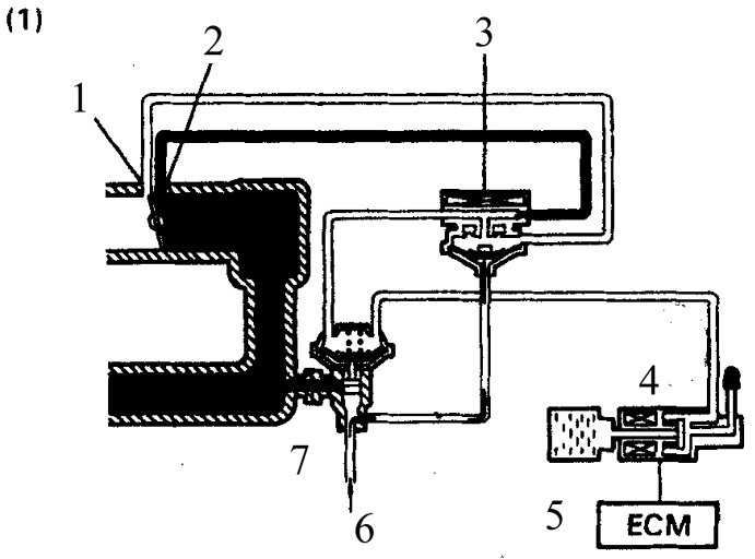
1. R port
2. E port
3. Vacuum switching valve (VSV)
4. Vacuum modulator
5. ECU
6. From exhaust manifold
7. EGR valve
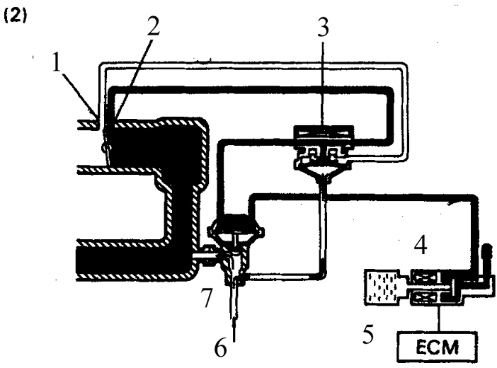
1. R port
2. E port
3. Vacuum switching valve (VSV)
4. Vacuum modulator
5. ECU
6. From exhaust manifold
7. EGR valve
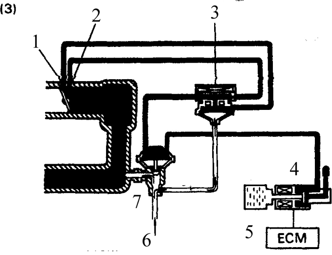
1. R port
2. E port
3. Vacuum switching valve (VSV)
4. Vacuum modulator
5. ECU
6. From exhaust manifold
7. EGR valve

1. R port
2. E port
3. Vacuum switching valve (VSV)
4. Vacuum modulator
5. ECU
6. From exhaust manifold
7. EGR valve
Typical EGR System Operation Diagram
Part 1
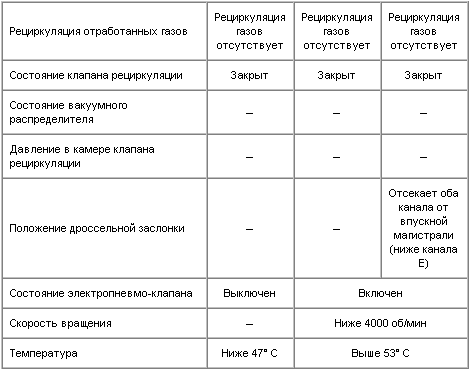
Part 2
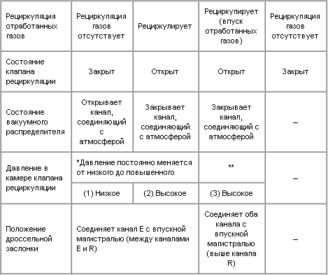
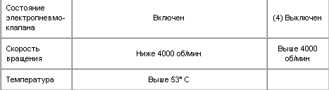
** When the throttle valve connects both distributor ports to the intake manifold, the distributor opens the EGR valve by the vacuum created, allowing exhaust gas to enter even at low exhaust pressure.
*** The vacuum switching valve is energized when the product of engine speed and the vacuum sensor reading exceeds a specified value.
**** When terminals TE1 and E1 of the data link connector are jumpered, the vacuum switching valve is energized.
To reduce nitrogen oxide emissions, combustion temperature is lowered by redirecting part of the exhaust gases through the EGR valve into the intake manifold.
This system is installed on vehicles sold in regions with strict exhaust emission regulations.
The EGR system consists of the EGR valve, vacuum modulator, vacuum switching valve, electronic control unit, and temperature sensor.
EGR VALVE
Inspection
PROCEDURE
1. Start the engine and let it idle.
2. Disconnect the vacuum hose from the EGR valve and connect a portable vacuum pump in its place.
3. Apply vacuum to the EGR valve. The vacuum must hold steady, and the engine should begin to run roughly.
4. If the vacuum does not hold and the engine keeps running smoothly, replace the EGR valve.
5. If the vacuum gauge shows steady vacuum but the engine runs smoothly, remove the EGR valve and check the valve and intake manifold for cleanliness. Clean or replace these parts as necessary.
VACUUM MODULATOR FILTER
Inspection
PROCEDURE
1. Remove the vacuum modulator.
2. Remove the cover and check the condition of the filters.
3. Clean or replace the filters, then install the cover and the vacuum modulator.
EGR SYSTEM
Inspection
PROCEDURE
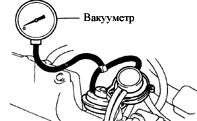
1. Disconnect the hose from the EGR valve and connect the vacuum modulator to the EGR valve through a tee with a vacuum gauge.
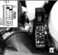
2. Start the engine and jumper terminals TE1 and E1 of the diagnosis connector.
3. While the engine is cold (coolant temperature below 45 °C), confirm that at 2500 rpm the vacuum gauge shows no reading. On a warm engine at 2500 rpm, the vacuum gauge should show low vacuum. On a fully warm engine, when engine speed is increased to 2500 rpm, the vacuum gauge should also show low vacuum.
4. Check the vacuum switching valve. The vacuum switching valve is mounted on the intake manifold.
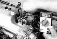
5. Check the resistance of the vacuum switching valve, which should be between 37 and 44 ohms.
6. If the check results are unsatisfactory, replace the vacuum switching valve.
EGR VALVE
Component Replacement
PROCEDURE
1. Disconnect the battery ground cable.
2. Remove the air cleaner housing.
3. Disconnect the throttle cable from the throttle body (see subsection 5.12).
4. Remove the throttle body from the intake manifold (see subsection 5.12).
5. Remove the vacuum modulator (see below).
6. Remove the EGR tube.
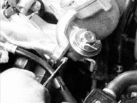
7. Remove the mounting bolts of the EGR valve and remove the valve.
8. Install the EGR valve in the reverse order of removal.
EGR VACUUM MODULATOR
Replacement
PROCEDURE
1. Disconnect the vacuum hoses, marking them beforehand, and remove the vacuum modulator from the bracket.
2. Install the vacuum modulator in the reverse order of removal.
Test yourself
A quick Toyota Corolla quiz: every answer comes with an explanation and a link to the manual page.