Electronic Control System
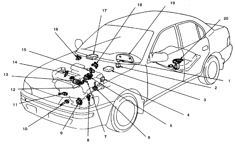
Location of Engine Control and Emission Control System Components
1. Ignition switch
2. Fuel pump relay
3. Engine control module (ECM)
4. Data link connector 1
5. Idle air control valve
6. Auxiliary oxygen sensor (1*)
7. Intake manifold air temperature sensor
8. Vehicle speed sensor
9. Park/Neutral position switch (2*)
10. Oxygen sensor
11. Main oxygen sensor (2*)
12. Engine coolant temperature sensor
13. Toyota Integrated Ignition Assembly (IIA)
14. Injector
15. Throttle position sensor (TPS)
16. Manifold absolute pressure sensor (MAP sensor)
17. Air conditioning amplifier
18. Idle speed compensation solenoid valve when air conditioning is switched on
19. Instrument cluster
20. Fuel pump
1* California vehicles only
2* Vehicles with automatic transmission only
The fuel injection system is controlled by an on-board microcomputer called the Electronic Control Module (ECM).
The electronic control module receives information from various sensors that monitor engine operating parameters such as intake air volume and temperature, engine coolant temperature, engine speed, acceleration or engine braking mode, oxygen concentration in the exhaust gas, etc. The electronic control module uses these signals to correctly determine the fuel injection duration. Based on the data received from the sensors, the control module determines the optimal fuel injection duration. The system is similar to the human central nervous system. The sensors (nerve endings) constantly send signals to the electronic control module (the "brain" of the system), which processes the received data and, when necessary, sends commands to change the engine operating parameters (to the "body").
The following is an example of how part of this system operates.
The oxygen sensor installed in the exhaust manifold constantly monitors the oxygen content in the exhaust gas. If the oxygen percentage in the exhaust gas is above the norm, an electrical signal is sent to the electronic control module. The electronic control module receives this information, processes it, and then sends a command to the fuel injection control system to change the air-fuel mixture composition. With the engine running, this takes place within fractions of a second and continues constantly. The end result is that the air-fuel mixture composition is maintained at the specified level regardless of driving conditions.
If the sensor fails, a backup circuit simulating the faulty sensor is activated, which maintains the vehicle's drivability until the fault is corrected.
* The vehicles in question are equipped with airbags. At any time, with the battery connected, the airbag (which has a rigid construction) may deploy (inflate). To prevent accidental airbag deployment (and possible injury) when performing any work near airbag components, turn the ignition key to the Lock position and disconnect the battery ground cable. After disconnecting the battery, wait two minutes (required for the backup capacitor to fully discharge). A more detailed description is given in Subsection 12.24.
Before disconnecting the battery ground cable, make sure you know the radio unlock code (if the radio is equipped with an anti-theft lock device).
Observe the following precautions:
– Before disconnecting any electrical connectors, always switch off the vehicle electrical system by turning the ignition key to the OFF position, or by disconnecting the battery from ground;
– When installing the battery, observe the correct cable polarity;
– Do not subject the electronic fuel injection system and emission control system components to strong impacts during removal or installation;
– Be careful during troubleshooting. Even a brief short circuit between connector terminals may lead to incorrect test results or damage to one of the numerous transistor circuits;
– Do not attempt to repair the control module or open the electronic control module housing cover;
– Do not allow water to get onto system sensors during inspection in rainy weather. When washing the engine compartment, do not spray water onto the sensors and control system connectors.
Test yourself
A quick Toyota Corolla quiz: every answer comes with an explanation and a link to the manual page.