Generator Components
Inspection of Positive Side Rectifier Bridge Diodes
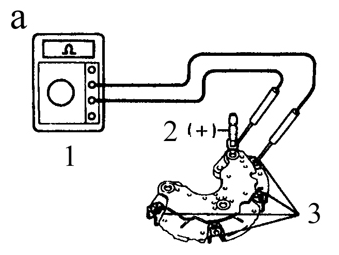
a) For vehicles from the USA:
1. Ohmmeter
2. Positive terminal
3. Diode terminals
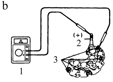
b) For vehicles from Canada:
1. Ohmmeter
2. Positive terminal
3. Diode terminals
Inspection of Negative Side Rectifier Bridge Diodes

a) For vehicles from the USA:
1. Ohmmeter
2. Negative terminal

b) For vehicles from Canada:
1. Ohmmeter
2. Negative terminal
Disassembly
PROCEDURE
1. Remove the generator (see subsection 3.3.11), place the generator on a clean workbench.

2. Remove the rear cover nuts and the generator output terminal nut. Remove the output terminal insulating bushing and the rear cover.
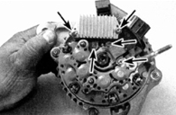
3. Remove the five screws securing the voltage regulator and brush holder (indicated by arrows).
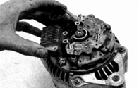
4. Remove the voltage regulator and brush holder from the generator housing rear flange. If only the voltage regulator is being replaced, perform step 8, install the new regulator, assemble the generator and install it on the engine. If the brushes are being replaced, follow the next step of this procedure.
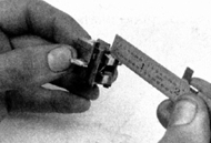
5. Measure the protruding length of the brushes and compare it with the minimum length specified in the 'Technical Data' section. If the brush length is less than the minimum, replace the brush holder assembly with brushes.
* On some vehicles, only the brushes can be replaced by resoldering them.
6. Make sure the brushes move freely in the brush holder.
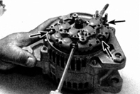
7. Remove the rectifier (arrows indicate the rectifier mounting screws). Remove the four rubber buffers and the dust deflector.
8. Make alignment marks on the front and rear covers to facilitate assembly.
9. Remove the pulley nut from the rotor and remove the pulley.
10. Remove the four nuts securing the front cover to the rear flange, and separate the generator rear flange from the cover.
11. Remove the thrust washer and remove the rotor from the front cover.
Inspection
PROCEDURE
1. Check the resistance of the circuit between the two slip rings. Resistance should be 2–4 Ω.
2. Check the circuit between the rotor shaft and the slip rings. The ohmmeter should show infinite resistance (there should be no contact between the rotor and the rings). If the results of both checks are unsatisfactory, or if the rings are excessively worn, replace the rotor.
3. Check the resistance between the stator winding terminals. If the resistance is high or the ohmmeter shows an open circuit, the stator must be replaced. Check the stator windings for grounding to the housing (core). If the ohmmeter shows finite resistance between the stator terminals and the housing, the stator is faulty.
4. Check the positive and negative side diodes of the rectifier bridge. To do this, place the positive ohmmeter probe on the output stud (arrow at top), and the negative probe on any of the diode terminals shown in the illustration (arrow at bottom).
5. Then reverse the probes and touch the same terminals.
6. On the first connection the ohmmeter should show continuity, and on reversed connection an open circuit (see figure Inspection of Positive Side Rectifier Bridge Diodes). Check the resistance between the remaining terminals in the same way. If at least one diode fails the test, the diode circuit is considered faulty.
7. Now check the negative side diodes of the rectifier bridge. Place the negative ohmmeter probe on the negative terminal (see figure Inspection of Negative Side Rectifier Bridge Diodes), and the positive probe on any rectifier terminal. Then reverse the probes and touch the same terminals. On the first connection the ohmmeter should show an open circuit, and on reversed connection continuity. Check the resistance between the remaining terminals in the same way. If at least one diode fails the test, the diode circuit is considered faulty.
Assembly
PROCEDURE
1. Installation is performed in reverse order, observing the following rules.
2. When installing the brush holder on the shaft, press the brushes back with a small screwdriver.
3. Screw the voltage regulator and brush holder mounting screws into the generator rear flange.
4. Install the rear cover and tighten the three nuts.
5. Install the output terminal insulating bushing and tighten the nut.
6. Install the generator on the vehicle.
Test yourself
A quick Toyota Corolla quiz: every answer comes with an explanation and a link to the manual page.