Charging System
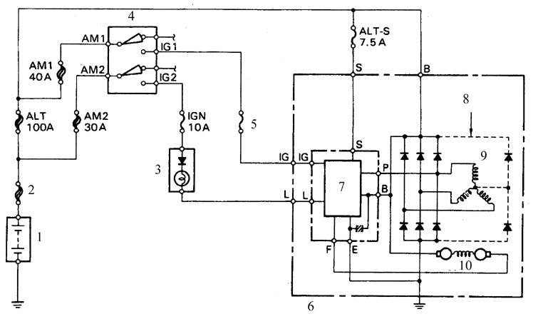
Battery Charging Circuit Diagram 1. Battery
2. Main fusible link
3. Charge warning lamp
4. Ignition switch
5. GAUGE fuse, 10 A
6. Alternator
7. Built-in voltage regulator
8. US models only
9. Stator winding
10. Rotor winding
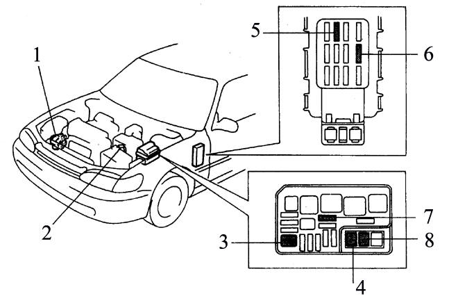
Typical Fusible Link and Fuse Locations 1. Alternator
2. Main fusible link
3. AM2 fuse, 30 A
4. AM1 fuse, 40 A
5. IGN fuse, 10 A
6. GAUGE fuse, 10 A
7. ALT-S fuse, 7.5 A
8. ALT-H fuse, 100 A

Battery Discharge Current Test Circuit
1. Ammeter
2. Battery
3. Disconnect the wire from terminal B
4. Voltmeter
5. Alternator
The charging system consists of an AC alternator with an integral voltage regulator, the charge warning lamp circuit, the battery, the main fusible link and connecting wires (see illustration Battery Charging Circuit Diagram). Together, these components supply power to the ignition system, lighting and signaling devices, radio, and other electrical loads. The alternator is driven by a belt at the front of the engine.
The vehicles covered by this manual are equipped with alternators manufactured by Nippondenso and Delco.
The voltage regulator maintains the alternator output voltage at a specified level. When the alternator output voltage rises sharply, the regulator prevents current surges and overloading of the power supply circuit.
The main fusible link is a separate length of wire connected in series with the battery cable harness, located inside the engine compartment (see illustration Typical Fusible Link and Fuse Locations). In addition to the main fusible link, the charging system includes additional fuses, which are short lengths of wire with a precisely specified cross-sectional area.
The cross-sectional area of the fuses is smaller than that of the wiring of the circuit they protect. Refer to subsection 12.2 for more detailed information on fuses.
Periodic maintenance of the charging system is generally not required. However, the alternator drive belt, battery and connecting wires should be inspected periodically (inspection interval: every 12,000 km or 6 months).
The charge warning lamp on the instrument panel illuminates when the ignition is switched on and goes out after the engine starts. If the lamp remains on after the engine starts, there is a fault in the charging circuit. Some vehicles are equipped with a voltmeter. If the voltmeter shows a very high or very low voltage, the charging circuit should be checked (refer to subsection 3.3.4).
Warning
When connecting the wires of the vehicle's internal circuit and external devices, observe the following precautions:
– When connecting the battery to the alternator, always observe the correct polarity.
– Before performing any electric arc welding on the vehicle, disconnect the wires from the alternator and from the battery terminal.
– Never start the engine with the charger connected.
– Before connecting the charger, always disconnect the vehicle circuit cables from both battery terminals.
– Keep hands, hair and loose clothing away from the alternator belt while the engine is running.
– The alternator is connected directly to the battery, so short-circuiting the alternator terminals or overloading the alternator may cause arcing and fire.
– Before steam cleaning the engine, cover the alternator with polyethylene film and secure the film with a rubber band.
Inspection
PROCEDURE
1. Check the condition and tension of the alternator belt. If there are signs of wear, replace the belt.
2. Check the tightness of the alternator mounting bolts and the belt tension adjusting bolt.
3. Check the alternator and voltage regulator wiring, the security of the mounting, and the condition of the connectors.
4. Check the fusible link connected to the battery positive terminal and the fusible links located inside the engine compartment. If a fuse has blown, determine and eliminate the cause, then replace the fuse (if the fuse has blown, the engine will not start and the vehicle's electrical devices will not operate).
5. Check the condition of all fuses included in the battery charging circuit (see figure: Typical location of the fusible link and fuses). The installation location of the fuses depends on the model year of the vehicle; however, all fuses have the same designations. Main fusible link – 3.0W; fuses: Alt H (80–100 A), AM1 (40 A), AM2 (30 A), IG (10 A), Gauge (10 A) and ALT-S (7.5 A).
6. Start the engine and check the noise produced by the alternator (a howling or squealing sound indicates worn bearings).
7. Check the electrolyte specific gravity of the battery. If the specific gravity is low, charge the battery (this item does not apply to maintenance-free batteries).
8. Check the state of charge of the battery (if a battery cell is faulty, the battery may overcharge).
9. Disconnect the cables from the battery (first from the negative terminal, then from the positive terminal).
* Before disconnecting the cables, make sure you know the radio decoding code (if the radio is equipped with an anti-theft lock). Check the condition of the battery terminals and cable terminal clamps. If necessary, clean the terminals and posts. Connect the cable to the positive battery terminal first, then to the negative terminal.
10. Check the battery voltage with the engine not running. The voltage should be approximately 12 V.
11. Start the engine and check the voltage again; it should now be 13.5 to 15.1 V.
12. Turn on the high beam headlights. If the charging system is operating normally, the voltage should drop and then rise again.
13. If the voltage is higher than the normal charging voltage, replace the voltage regulator.
14. If the voltage is lower than normal, check the regulator and the alternator as follows.
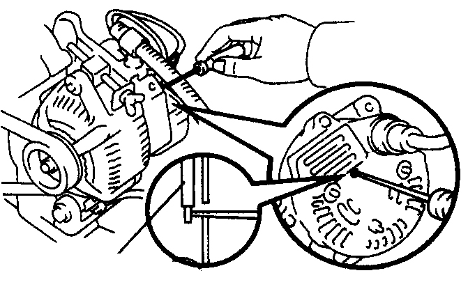
15. Remove the rear cover from the alternator, connect terminal F (indicated by the arrow) to ground, start the engine, read the battery voltage and compare it with the standard value. If the voltage is higher than the standard, replace the voltage regulator. If the voltage is lower than the standard, check the alternator (or, if no ammeter is available, take the vehicle to a service workshop).
16. If an ammeter is available, connect it into the charging circuit (see figure: Circuit for checking battery discharge current). If no ammeter is available, a current clamp (transformer-type ammeter) may be used. This tool is inexpensive, is always commercially available, and gives fairly accurate readings.
17. Increase the engine speed to 2000 rpm and measure the current with all electrical loads off. Then turn on the high beam headlights and the heater blower (set the switch to the HI position). Measure the current and compare it with the values given in subsection 3.3.1.
18. If the measured current is lower than the specified value, repair or replace the alternator.
Test yourself
A quick Toyota Corolla quiz: every answer comes with an explanation and a link to the manual page.