Ignition System
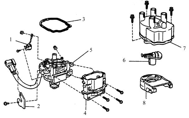
Components of the contactless ignition system with external electronic module
1. Capacitor
2. Wiring harness bracket
3. Gasket
4. Ignition coil
5. Distributor housing assembly
6. Rotor
7. Distributor cap
8. Ignition coil dust cover
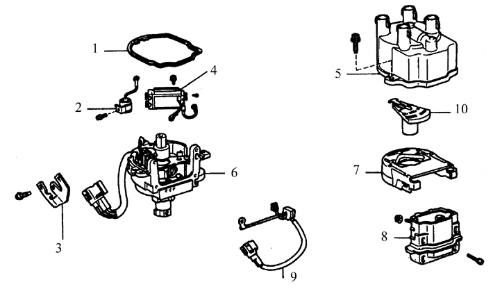
Components of the contactless ignition system with built-in electronic module
1. Gasket
2. Capacitor
3. Wiring harness bracket
4. Electronic ignition module
5. Distributor cap
6. Distributor housing assembly
7. Ignition coil dust cover
8. Ignition coil
9. Distributor wire
10. Rotor
The vehicles covered in this Manual are equipped with two types of ignition systems: a system with an external electronic module and a system with an internal ignition module. The latter differ in that the electronic ignition module (igniter) is built into the distributor housing. In both systems the ignition coil is mounted inside the distributor.
The electronic ignition system includes:
– ignition switch;
– battery;
– electronic ignition module;
– induction sensor;
– ignition coil;
– low-tension (primary) and high-tension (secondary) circuit wires;
– distributor and spark plugs.
The ignition system is controlled by the electronic control module (ECM). The ECM automatically adjusts ignition timing according to signals from sensors that monitor various engine parameters (such as engine speed, intake air volume, coolant temperature, etc.). This system is called an electronic spark advance control system (ESA system).
Contactless ignition systems are divided into two groups: systems with a built-in electronic ignition module and systems with an external electronic module (see Figure Components of the contactless ignition system with external electronic module and Figure Components of the contactless ignition system with built-in electronic module). Before replacing any ignition system component, make sure that all checks have been fully performed and that this particular component must be replaced. This is because parts are expensive and, as a rule, cannot be returned.
* When performing checks and repairs on the ignition system, observe the following safety rules:
– if the engine fails to start, do not leave the ignition switched on for more than 10 minutes;
– connect the tachometer in accordance with the manufacturer's instructions (consult the dealer service department before purchasing a tachometer);
– do not allow the ignition coil terminals to contact ground (otherwise the electronic ignition module and coil may fail);
– do not disconnect the battery ground cable while the engine is running;
– always make sure the electronic ignition module is securely grounded.
Inspection
* The ignition system generates very high voltage, so special care must be taken when working on it. Potential hazards include not only the electronic ignition module, coil, distributor and high-tension wires, but also auxiliary parts such as spark plug boot terminals, tachometers and other test and measuring instruments.
PROCEDURE
1. If the engine does not start but the starter cranks the crankshaft vigorously, disconnect the high-tension leads from the spark plugs and connect a calibrated spark tester (commercially available) to them. Connect one terminal of the tester to a bolt or metal bracket on the engine. If no spark tester is available, disconnect the lead from one of the spark plugs, pull back the insulating boot, and secure the lead with an insulated tool approximately 6.0 mm from a bare metal ground surface.
2. Crank the engine with the starter and observe the spark tester or the spark plug lead. A strong blue spark should appear.
3. If there is a spark, the required voltage is reaching the spark plugs (check the other leads to confirm that the distributor cap and rotor are good). Remove the spark plugs and inspect them (refer to Subsection 2.8.2).
4. If there is no spark, or the spark is unstable, remove the distributor cap and check the condition of the cap and rotor (Subsection 2.8.3). If moisture is found, wipe the cap and rotor dry, reinstall the cap, and repeat the test.
5. If there is still no spark, disconnect the coil high-tension lead from the distributor cap and connect the lead to the spark tester (reinstall the spark plug lead). Repeat the test. If no tester is available, secure the coil lead with an insulated tool approximately 6.0 mm from a bare metal ground surface.
6. If a spark now appears, the cause may be a faulty distributor cap or rotor.

7. If there is no spark, check the entire wiring of the ignition coil primary circuit and make sure the connections are clean and secure. Check whether voltage is supplied to the coil from the ignition switch. Check the ignition coil (refer to Subsection 3.3.5) and the distributor pickup coil (refer to Subsection 3.3.9). Perform the necessary repairs and repeat the test.
8. If there is still no spark, replace the lead connecting the ignition coil and the distributor cap (check the lead resistance and compare it with the specification given in Subsection 2.1). If replacing the lead with a known good one does not help, the electronic ignition module is faulty.
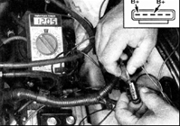
9. Check whether voltage is supplied from the battery to the electronic module when the ignition is switched on. If there is no voltage, replace the electronic module (refer to Subsection 3.3.8).
Test yourself
A quick Toyota Corolla quiz: every answer comes with an explanation and a link to the manual page.