Valve Clearance - Inspection and Adjustment
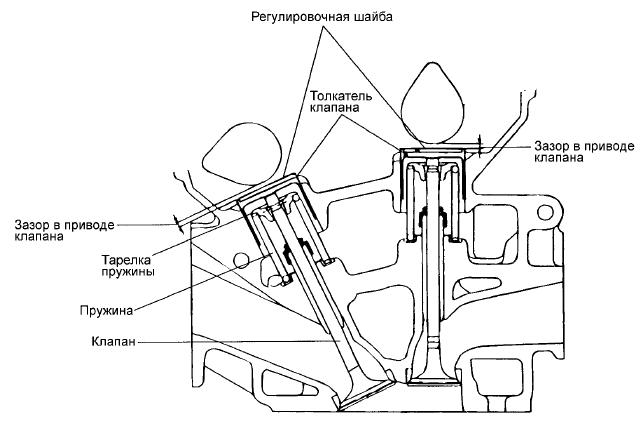
VALVE CLEARANCE
Inspect and adjust the valve clearance with the engine cold (coolant temperature: 20°C) and the cylinder head installed on the engine.
1. Remove the engine cover.
2. Remove the oil filler cap.
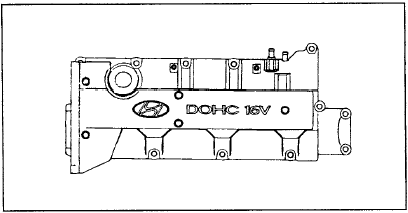
3. Remove the bolts securing the center cover, then remove the cover.
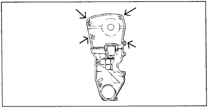
4. Remove the upper timing belt cover.
a) Remove the bolts securing the upper timing belt cover, then remove the cover.
5. Remove the cylinder head cover.
a) Disconnect the spark plug high-tension cables by holding the caps. Do not apply excessive force when disconnecting them.
Pulling or bending the high-tension cable may damage the conductor inside the cable.
b) Disconnect the positive crankcase ventilation (PCV) hose and the PCV valve hose from the cylinder head cover.
c) Disconnect the accelerator pedal cable from the cylinder head cover.
d) Remove the bolts securing the cylinder head cover, then remove the cover and gasket.
6. Set the No. 1 cylinder piston to top dead center (TDC) on the compression stroke.
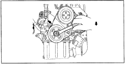
a) Turn the crankshaft pulley and align the groove on it with the "T" alignment mark on the timing mark indicator (scale on the lower timing belt cover).
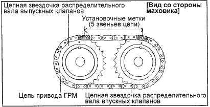
b) Check that the hole in the camshaft sprocket (for the belt) is aligned with the alignment mark on the front camshaft bearing cap. If they are not aligned, turn the crankshaft one full revolution (360°).
7. Check the valve clearance.
a) Check only the valves marked in the illustration (with the No. 1 cylinder piston at TDC on the compression stroke). Measure the valve clearance.
• Using a flat feeler gauge, measure the clearance between the valve lifter shim and the back (non-working) surface of the cam lobe.
• Record the clearance measurements at locations where the measured value does not meet the specification. This data will be required later to select the replacement shim.
Valve clearance (with engine coolant temperature: 20 °C) [Standard value] Intake valves: 0.20 mm Exhaust valves: 0.28 mm [Allowable limit] Intake valves: 0.12 - 0.28 mm Exhaust valves: 0.20 - 0.36 mm
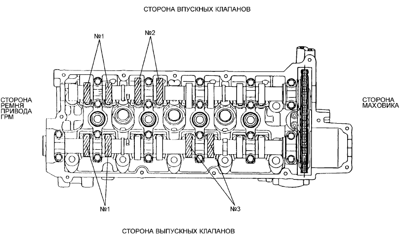
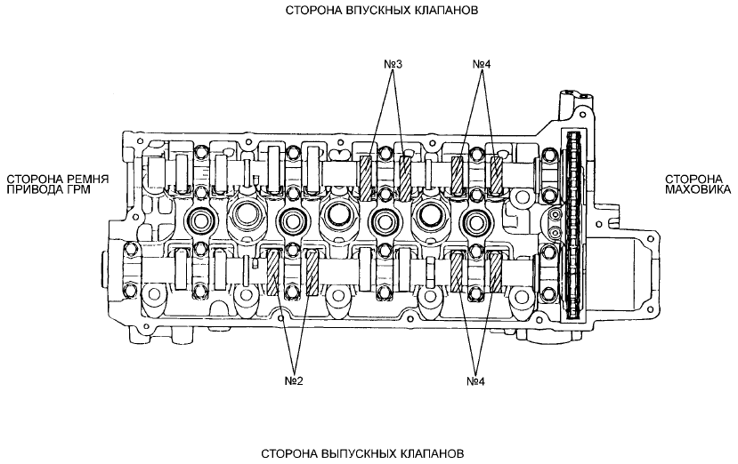
b) Turn the crankshaft pulley one full revolution (360°) and align the groove on it with the "T" alignment mark on the timing mark indicator (scale on the lower timing belt cover).
c) Check only the valves marked in the illustration [with the No. 4 cylinder piston at TDC on the compression stroke]. Measure the valve clearance. (Refer to the procedure in step (1).)
8. Adjust the intake and exhaust valve clearance.
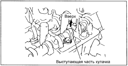
a) Turn the crankshaft so that the lobe of the camshaft for the valve being adjusted points upward.
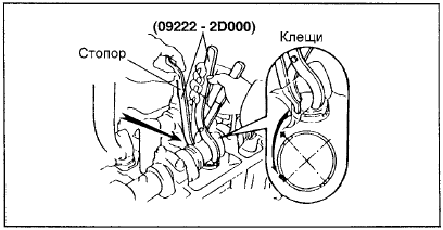
b) Using the special service tool (09220-2D000), press down the valve lifter and insert a stopper between the camshaft and the valve lifter. Remove the special service tool.
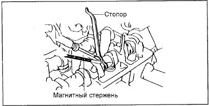
c) Using a small screwdriver and a magnet, remove the valve lifter shim.
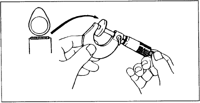
d) Using a micrometer, measure the thickness of the removed shim.
e) Calculate the thickness of the new shim required to bring the valve clearance to the standard value.
Valve clearance (with engine coolant temperature: 20 °C) T: Thickness of the installed shim A: Measured valve clearance N: Thickness of the new shim Intake valve: N = T + [A - 0.20] mm Exhaust valve: N = T + [A - 0.28] mm f) Select a new shim with a thickness as close as possible to the calculated value. [Refer to the "Valve Lifter Shim Selection Table."]
20 sizes of valve lifter shims are available, in 0.04 mm increments, ranging from 2.0 mm to 2.76 mm.
g) Install the selected shim onto the valve lifter.
h) Using the special service tool (09220-2D000), press down the valve lifter and remove the stopper.
i) Check the valve clearance again.
Valve clearance (with engine coolant temperature: 20 °C) [Standard value] Intake valves: 0.20 mm Exhaust valves: 0.28 mm [Allowable limit] (after adjustment) Intake valves: 0.17 - 0.23 mm Exhaust valves: 0.25 - 0.31 mm
Test yourself
A quick Hyundai Elantra CN7 quiz: every answer comes with an explanation and a link to the manual page.