Piston and Connecting Rod - Inspection
PISTON AND PISTON PIN 1. Inspect each piston for scratches, scoring, wear and other defects. Replace the piston if any defects are found.
2. Inspect each piston ring for breakage, damage or excessive wear. Replace any defective rings. If the piston is replaced, its piston rings must be replaced at the same time.
3. Check that the piston pin fits into the piston bosses. If defects are found, replace the piston and piston pin as a set. At room temperature, the piston pin should enter the piston bore easily, without binding, under hand pressure.
PISTON RINGS
1. Measure the clearance between the piston ring and the piston ring groove. If the measured clearance exceeds the service limit, install a new piston ring and measure the clearance again. If the measured clearance still exceeds the service limit, replace the piston and rings as a set. If the measured clearance is less than the service limit, replace only the piston rings.
Piston Ring Groove Clearance [Standard Value] No. 1 Compression Ring: 0.04 - 0.08 mm No. 2 Compression Ring: 0.03 - 0.07 mm [Service Limit] No. 1 Compression Ring: 0.1 mm No. 2 Compression Ring: 0.1 mm 2. To measure the piston ring end gap, insert the piston ring into the cylinder bore. Position the ring at a right angle to the cylinder wall, carefully pushing it down with the piston. Measure the ring end gap with a feeler gauge. If the measured gap exceeds the service limit, replace the piston ring.
Piston Ring End Gap [Standard Value] No. 1 Compression Ring: 0.23 - 0.38 mm No. 2 Compression Ring:
[1.8L Engine]: 0.45 - 0.60 mm [2.0L Engine]: 0.33 - 0.48 mm Oil Control Ring: 0.20 - 0.60 mm [Service Limit] No. 1 and No. 2 Compression Rings: 1.0 mm Oil Control Ring: 1.0 mm
4. When replacing piston rings without boring the cylinders to an oversize, check the ring end gap at a point near the bottom of the cylinder (the area of least wear).
Piston Ring Oversize and Identification Mark Standard Size: No mark 0.25 mm: 25 0.50 mm: 50 0.75 mm: 75 1.00 mm: 100
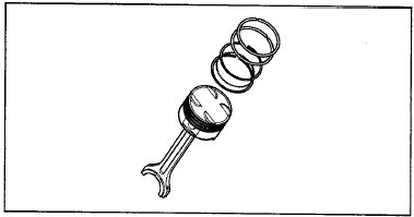
The oversize identification mark is located on the upper surface of the piston ring, near the ring end gap.
CONNECTING RODS
1. When installing the connecting rod cap, make sure the cylinder number marks (made during disassembly) on the connecting rod and the cap are aligned. When installing a new connecting rod, make sure the bearing locking tabs in the cap and the connecting rod are on the same side.
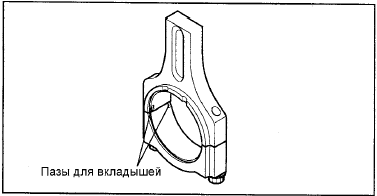
2. Replace the connecting rod if the end face of the upper or lower connecting rod eye is damaged. Replace the connecting rod if it is bent or twisted, or if the piston pin bore in the upper connecting rod eye is excessively worn.
Test yourself
A quick Hyundai Elantra CN7 quiz: every answer comes with an explanation and a link to the manual page.