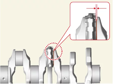
Check the connecting rod side clearance. Using a feeler gauge, measure the end play while moving the connecting rod back and forth.
If out-of-tolerance, install a new connecting rod.
If still out-of-tolerance, replace the crankshaft.
Side clearance Specified value : 0.100 - 0.250 mm (0.0039 - 0.0098 in.)
Inspect the oil clearance of connecting rod bearing.
Check the match marks on the connecting rod and cap are aligned to ensure correct reassembly.
Remove the 2 connecting rod cap bolts.
Remove the connecting rod cap and lower bearing.
Clean the crankshaft pin journal and bearing.
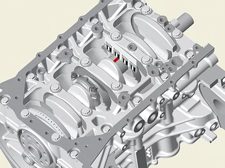
Place a plastigage across the crankshaft pin journal.
Reinstall the lower bearing and connecting rod cap and tighten the bolts to the specified torque. (However, do not reuse the bolts.) Tightening torque 1st step : 17.7 - 22 N·m Step 2 : 98 - 102°
If the plastigage shows the clearance is still incorrect, try the next larger or smaller bearing. Recheck the oil clearance.
Do not file, shim, of scrape the bearings or the caps to adjust clearance.
If the plastigage shows the clearance is still incorrect, try the next larger or smaller bearing. Recheck the oil clearance.
If the proper clearance cannot be obtained by using the appropriate larger or smaller bearings, replace the crankshaft and repeat the check procedure.
If the marks are indecipherable because of an accumulation of dirt and dust, do not scrub them with a wire brush or scraper. Clean them only with solvent or detergent.
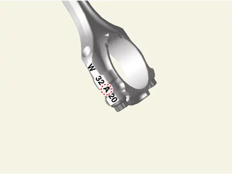
Classification Mark Position For Connecting Rod Classification table for connecting rod
Class
Mark
Inside Diameter
0
A
48.000 - 48.006 mm (1.88976 - 1.89000 in.)
1
B
48.006 - 48.012 mm (1.89000 - 1.89023 in.)
2
C
48.012 - 48.018 mm (1.89023 - 1.89047 in.)
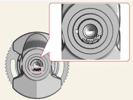
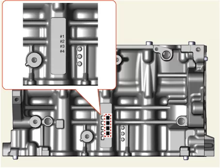
Classification mark position for outer diameter of crankshaft pin
Conform to read stamping order as shown arrow direction from #1.
Identification Of Crankshaft Pin Outside Diameter
Class
Mark
Pin journal diameter
I
1
44.966 - 44.972 mm (1.77031 - 1.77055 in.)
II
2
44.960 - 44.966 mm (1.77008 - 1.77031 in.)
III
3
44.954 - 44.960 mm (1.76984 - 1.77008 in.)
Connecting Rod Bearing Identification Mark Classification Table For Connecting Rod Bearing
Class
Mark
A
Light Blue
1.510 - 1.513 mm (0.05944882 - 0.059566929 in.)
B
Black
1.507 - 1.510 mm (0.059330709 - 0.05944882 in.)
C
White
1.504 - 1.507 mm (0.059212598 - 0.059330709 in.)
D
Light Green
1.501 - 1.504 mm (0.059094488 - 0.059212598 in.)
E
Pink
1.498 - 1.501 mm (0.058976378 - 0.059094488 in.)
Select the proper connecting rod bearing using the below bearing selection table. Selection Table For Connecting Rod Bearing
Connecting Rod Identification Mark
0
1
2
Crankshaft Identification Mark
I (1)
E (Pink)
D (Light Green)
C (White)
II (2)
D (Light Green)
C (White)
B (Black)
III (3)
C (White)
B (Black)
A (Light Blue)
Check the connecting rods.
When reinstalling, make sure that cylinder numbers put on the connecting rod and cap at disassembly match. When a new connecting rod is installed, make sure that the notches for holding the bearing in place are on the same side.
Replace the connecting rod if it is damaged on the thrust faces at either end. Also if step wear or a severely rough surface of the inside diameter of the small end is apparent, the rod must be replaced as well.
Measure the bending and torsion of the rod using a connecting rod aligner, and if the measured value is close to the limit, correct the rod using a press. If the bending and torsion are excessive, replace the connecting rod. 0.05 mm (0.0020 in.) or less for 100 mm (3.94 in.) Allowable twist of connecting rod : 0.10 mm (0.0039 in.) or less for 100 mm (3.94 in.)
When the connecting rods are installed without bearings, there should be no difference on side surface.
Clean the piston.
Using a gasket scraper, remove the carbon from the piston top.
Using a groove cleaning tool or broken ring, clean the piston ring grooves.
Using solvent and a brush, thoroughly clean the piston.
Do not use the wire brush.
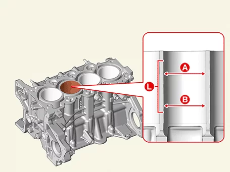
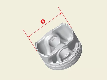
Check the piston-to-cylinder clearance by calculating the difference between the cylinder bore inner diameter and the piston outer diameter.
Check the cylinder bore size code on the cylinder block side surface. Cylinder Bore Size Classification Table
Cylinder Bore Inner Diameter
A
81.00 - 81.01 mm (3.1890 - 3.1894 in.)
B
81.01 - 81.02 mm (3.1894 - 3.1898 in.)
C
81.02 - 81.03 mm (3.1898 - 3.1902 in.)
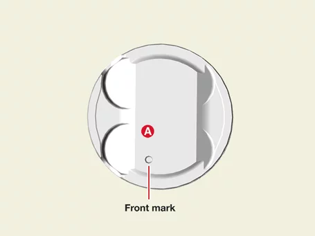
Check the piston outer diameter size indication on the upper surface of the piston. Piston Outer diameter Size Classification Table
Piston outer diameter
A
80.965 - 80.975 mm (3.1876 - 3.1880 in.)
B
80.975 - 80.985 mm (3.1880 - 3.1884 in.)
C
80.985 - 80.995 mm (3.1884 - 3.1888 in.)
Inspect the piston ring side clearance. Measure the clearance between the piston ring groove and the piston ring using a feeler gauge. Piston ring groove width Piston ring (NO.1) (A) : 0.040 - 0.080 mm (0.0016 - 0.0031 in.) Piston ring (NO.2) (B) : 0.040 - 0.080 mm (0.0016 - 0.0031 in.) Oil ring 0.070 - 0.125 mm (0.0027 - 0.0049 in.) If the clearance is over than limit value, replace the piston.
Inspect piston ring end gap.
Insert the piston ring into the cylinder to measure the end gap of the piston ring.
At this time, gently push the ring with the piston so that the ring is positioned at the correct angle with the cylinder wall.
Measure the end gap using a filler gauge and replace the piston ring if the measured value exceeded the limit value.
piston ring end gap Specifications Piston ring (NO.1) (A) : 0.15 - 0.30 mm (0.0059 - 0.0118 in.) Piston ring (NO.2) (B) : 0.30 - 0.45 mm (0.0118 - 0.0177 in.) Oil ring: 0.10 - 0.40 mm (0.003937 - 0.015748 in.)