Cylinder head cover
Bauteile und bauteile-Übersicht
BAUTEILE-ÜBERSICHT
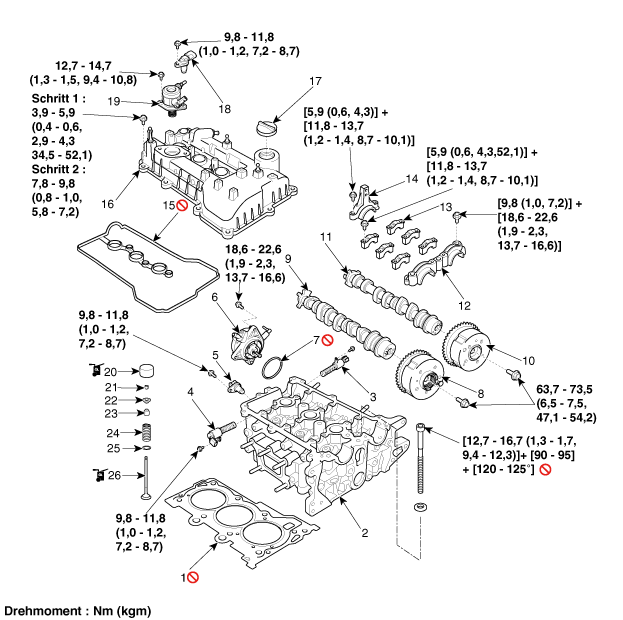
| 1. Cylinder head gasket 2. Cylinder head 3. Intake Oil Control Valve (OCV) 4. Exhaust Oil Control Valve (OCV) 5. Exhaust Camshaft Position Sensor (CMPS) 6. Vacuum pump 7. Vacuum pump O-ring 8. Exhaust CVVT assembly 9. Exhaust camshaft |
10. Intake CVVT assembly 11. Intake camshaft 12. Camshaft bearing cap 13. Middle camshaft bearing cap 14. Rear camshaft bearing cap 15. Valve cover gasket 16. Cylinder head cover 17. Oil filler cap 18. Intake Camshaft Position Sensor (CMPS) |
19. High pressure fuel pump 20. Mechanical valve lash adjuster (MLA) 21. Valve keeper 22. Valve retainer 23. Valve stem seal 24. Valve spring 25. Valve spring seat 26. Valve |
Repair Procedures
VALVE CLEARANCE INSPECTION AND ADJUSTMENT
Zylinderkopfdeckel abbauen.
(Refer to Cylinder Head - "Cylinder Head Cover")
Set No. 1 cylinder to TDC (compression stroke).
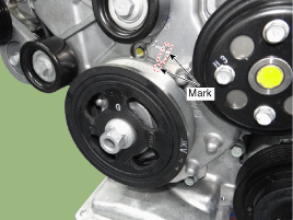
Turn the crankshaft pulley and align its groove with the timing mark "T" on the timing chain cover.
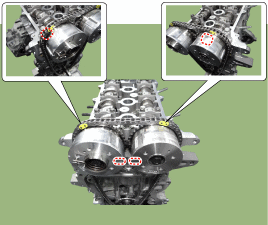
Check that the TDC marks on the intake CVVT sprocket and exhaust camshaft sprocket form a straight line with the cylinder head surface, as shown in the illustration.
Falls nicht, Kurbelwelle um eine Umdrehung (360°) drehen.
Ventilspiel prüfen.
Check only the valves shown (1st intake and 1st or 2nd exhaust). Measure valve clearance.
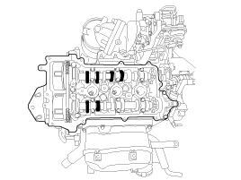
Mit einer Fühlerlehre das Spiel zwischen neuem Ventilstößel und Umlaufkreis der Nockenwelle messen.
Record the measurements outside tolerance. They will be used later to determine the required shims.
Valve clearance [Coolant temperature: 20 °C]
[Specification]
INTAKE:
0.20 ~ 0.26 mm
EXHAUST:
0.39 ~ 0.45 mm
Einlass- und Auslass-Nockenwellen um 210° im Uhrzeigersinn drehen.
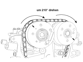
Check only the valves shown (2nd and 3rd intake and 3rd exhaust). Measure valve clearance.
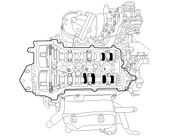
Einlass- und Auslassventilspiel einstellen.
Kolben des 1. Zylinders auf den OT des Kompressionshubs stellen.
Remove the camshaft.
(Refer to Cylinder Head - "CVVT and Camshaft")
Stärke des ausgebauten Stößel mit einer Mikrometerschraube messen.
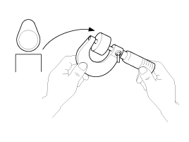
Die Stärke eines neuen Ventilstößels so berechnen, dass das Ventilspiel innerhalb des angegebenen Werts Liegt.
Valve clearance [Coolant temperature: 20 °C]
T: Stärke des ausgebauten Stößels
A: Measured valve clearance
N: Thickness of new shim
Intake: N = T + [A - 0.2 mm]
Exhaust: N = T + [A - 0.25 mm]
Einen neuen Ventilstößel wählen, dessen Stärke dem berechneten Wert am nächsten Liegt.
After applying engine oil to the outer circumference and top of the selected tappet, carefully insert the tappet into the cylinder head.
Einlass- und Auslassnockenwellen einbauen.
(Refer to Cylinder Head - "CVVT and Camshaft")
Kurbelwelle um zwei Umdrehungen in Laufrichtung (Uhrzeigersinn) drehen und kontrollieren, ob die OT-Markierungen der CVVT-Räder eine gerade Linie mit der Zylinderkopffläche bilden.
Ventilspiel nochmals prüfen.
Valve clearance [Coolant temperature: 20 °C]
[Specification]
INTAKE:
0.20 ~ 0.26 mm
EXHAUST:
0.39 ~ 0.45 mm
Test yourself
A quick Kia Stonic quiz: every answer comes with an explanation and a link to the manual page.