Engine Control System
Components and Component Location
Component Location
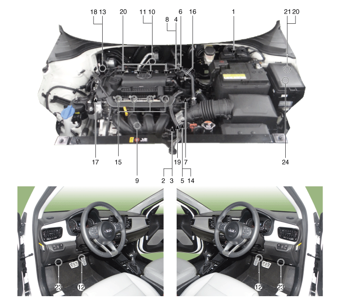
| 1. ECM (Engine Control Module) 2. Manifold Absolute Pressure Sensor (MAPS) 3. Intake Air Temperature Sensor (IATS) 4. Engine Coolant Temperature Sensor (ECTS) 5. Throttle Position Sensor (TPS) [Built into ETC Module] 6. Crankshaft Position Sensor (CKPS) 7. Camshaft Position Sensor (CMPS) [Bank 1/Intake] 8. Camshaft Position Sensor (CMPS) [Bank 1/Exhaust] 9. Knock Sensor (KS) 10. Heated Oxygen Sensor (HO2S) [Bank 1/Sensor 1] 11. Heated Oxygen Sensor (HO2S) [Bank 1/Sensor 2] 12. Accelerator Position Sensor (APS) |
13. Air Conditioning Pressure Sensor (APT) 14. ETC Motor [Built into ETC Module] 15. Injector 16. Purge Control Solenoid Valve (PCSV) 17. Variable Force Solenoid (VFS) [Bank 1/Intake] 18. CVVT Oil Control Valve (OCV) [Bank 1/Exhaust] 19. Variable Intake Solenoid (VIS) 20. Ignition Coil 21. Main Relay 22. Fuel Pump Relay 23. Data Link Connector (DLC) [16-pin] 24. Multi-Purpose Check Connector [6-pin] |
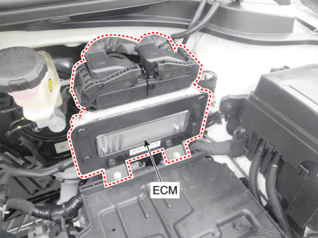
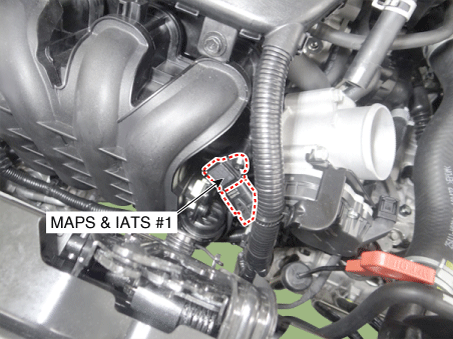
| 1. ECM (Engine Control Module) | 2. Manifold Absolute Pressure Sensor (MAPS) 3. Intake Air Temperature Sensor (IATS) |
 |
 |
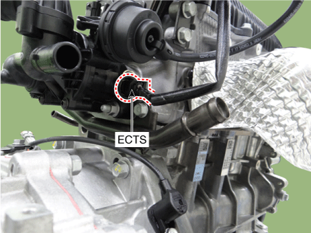
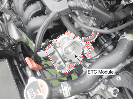
| 4. Engine Coolant Temperature Sensor (ECTS) | 5. Throttle Position Sensor (TPS) [Built into ETC Module] 14. ETC Motor [Built into ETC Module] |
 |
 |
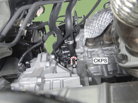
| 6. Crankshaft Position Sensor (CKPS) | 7. Camshaft Position Sensor (CMPS) [Bank 1/Intake] |
 |
 |
| 8. Camshaft Position Sensor (CMPS) [Bank 1/Exhaust] | 9. Knock Sensor (KS) |
 |
 |
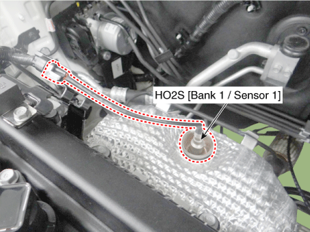
| 10. Heated Oxygen Sensor (HO2S) [Bank 1/Sensor 1] | 11. Heated Oxygen Sensor (HO2S) [Bank 1/Sensor 2] |
 |
 |
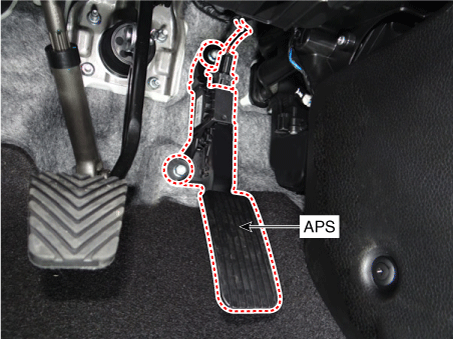
| 12. Accelerator Pedal Position Sensor (APS) | 13. Air Conditioning Pressure Sensor (APT) |
 |
 |
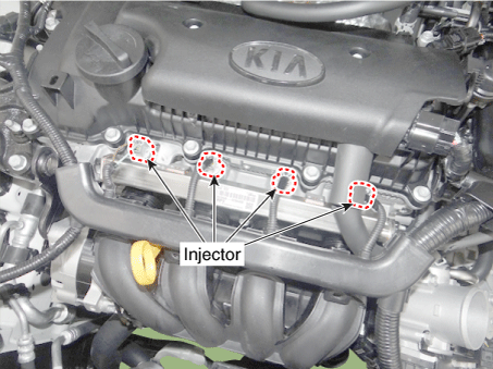
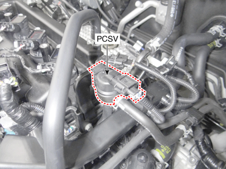
| 15. Injector | 16. Purge Control Solenoid Valve (PCSV) |
 |
 |
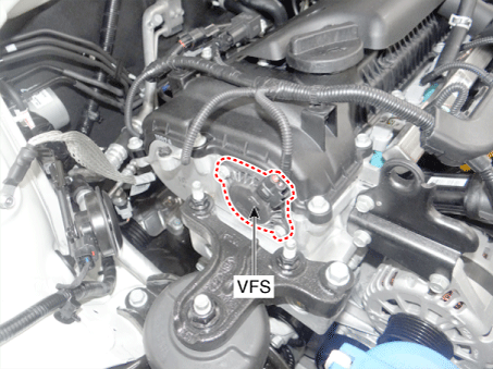
| 17. Variable Force Solenoid (VFS) [Bank 1/Intake] | 18. CVVT Oil Control Valve (OCV) [Bank 1/Exhaust] |
 |
 |
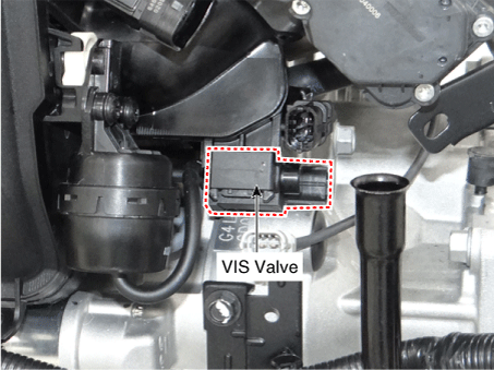
| 19. Variable Intake Solenoid (VIS) | 20. Ignition Coil |
 |
 |
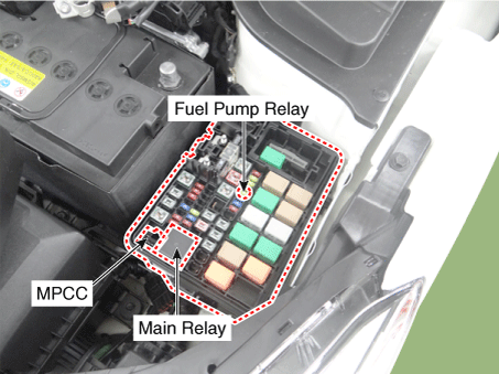
| 21. Main Relay [EMS Unit] 22. Fuel Pump Relay [EMS Unit] 24. Multi-Purpose Check Connector (MPCC) [6-pin] |
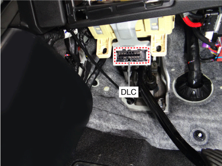
23. Data Link Connector (DLC) [16-pin] |
 |
 |
Description and Operation
Description
If any component of the gasoline engine control system (sensors, ECM, injectors, etc.) malfunctions, the engine may experience driveability problems, misfires, or be unable to receive the proper amount of fuel for various operating conditions. The following symptoms may occur.
Engine is hard to start or does not start at all.
Unstable idle.
Poor drivability
If any of the above conditions are present, first perform the general diagnostics, which include basic engine checks (ignition system malfunction, incorrect engine adjustment, etc.). Then inspect the gasoline engine control system components using HI-SCAN (Pro).
Malfunction Indicator Lamp (MIL)
[OBD]
The Malfunction Indicator Lamp (MIL) illuminates to notify the driver of a problem with the vehicle. However, the MIL turns off automatically after 3 consecutive driving cycles without the same malfunction. Immediately after the ignition switch is turned ON (engine not running), the MIL will stay on to indicate that the MIL is working properly.
Malfunctions with the following items illuminate the MIL.
Catalyst
Fuel System
Manifold Absolute Pressure Sensor (MAPS)
Intake Air Temperature Sensor (IATS)
Engine Coolant Temperature Sensor (ECTS)
ETC Module (TPS and ETC Motor)
Upstream Oxygen Sensor
Upstream Oxygen Sensor Heater
Downstream Oxygen Sensor
Downstream Oxygen Sensor Heater
Injector
misfire
Crankshaft Position Sensor (CKPS)
Camshaft Position Sensor (CMPS)
Evaporative Emission Control System
Vehicle Speed Sensor (VSS)
Power Supply
PCM/PCM
MT/AT Coding
Acceleration Sensor
MIL Request Signal
Power Stage
[NON-EOBD]
The Malfunction Indicator Lamp (MIL) illuminates to notify the driver of a problem with the vehicle. However, the MIL turns off automatically after 3 consecutive driving cycles without the same malfunction. Immediately after the ignition switch is turned ON (engine not running), the MIL will stay on to indicate that the MIL is working properly.
Malfunctions with the following items illuminate the MIL.
Heated Oxygen Sensor (HO2S)
Mass Air Flow Sensor (MAFS)
Throttle Position Sensor (TPS)
Engine Coolant Temperature Sensor (ECTS)
Idle Speed Control Actuator (ISCA)
Injectors
ECM
[Inspection]
After turning the ignition switch ON, make sure the indicator illuminates for about 5 seconds and then goes off.
If the lamp does not illuminate, check for an open circuit in the wiring harness, a blown fuse, or a burned-out bulb.
Self-Diagnosis
The ECM monitors input/output signals (some continuously, others under specific conditions). When the ECM detects a malfunction, it records a diagnostic trouble code (DTC) and outputs a signal to the Data Link Connector. Diagnostic results can be read using the MIL or HI-SCAN (Pro). DTCs remain stored in the ECM as long as battery power is supplied. However, DTCs will be erased when the battery terminal or ECM connector is disconnected, or by using HI-SCAN (Pro).
Relationship between DTC and Driving Pattern in EOBD System
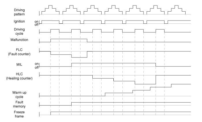
When the same malfunction is detected and stored during two consecutive driving cycles, the MIL will illuminate automatically.
The MIL will go off automatically if the malfunction is not detected after 3 consecutive driving cycles.
A diagnostic trouble code (DTC) is stored in the ECM memory when a malfunction is detected after two consecutive driving cycles. The MIL illuminates when the malfunction is detected during the second driving cycle.
When a misfire is detected, a DTC is stored and the MIL illuminates immediately after the malfunction is detected.
A Diagnostic Trouble Code (DTC) is automatically erased from the ECM memory if the same malfunction is not detected within 40 driving cycles.
Test yourself
A quick Kia Rio YB quiz: every answer comes with an explanation and a link to the manual page.