Horn Alarm Circuit
DESCRIPTION
When the anti-theft system changes from the armed state to the alarm sounding state, the main body ECU (multiplex network body ECU) outputs a signal to sound the security horn at 0.4-second intervals.
WIRING DIAGRAM
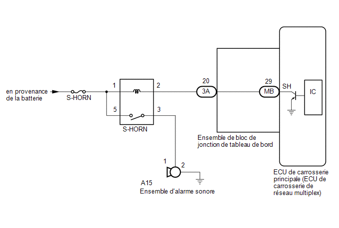
PRECAUTION / NOTICE / HINT
NOTICE:
- Before replacing the main body ECU (multiplex network body ECU), refer to the REGISTRATION section*1.
Click here

*1: with Smart Key System
- Check the fuses for the circuits related to this system before performing the following procedure.
PROCEDURE
PERFORM ACTIVE TEST USING TECHSTREAM (SECURITY HORN)
(a) Connect the Techstream to the DLC3.
(b) Turn the ignition switch to ON.
(c) Turn on the Techstream.
(d) Select the following menu items: Body Electrical / Main Body / Active Test.
(e) Perform the Active Test by following the Techstream instructions.
Body Electrical > Main Body > Active TestTester display | Item | Control Range | Diagnostic Note |
|---|---|---|---|
Security Horn |
Audible alarm unit |
OFF / ON |
- |
Security Horn
OK:
The security horn assembly sounds and stops in accordance with the Techstream command.
| OK |  |
REPLACE MAIN BODY ECU (MULTIPLEX NETWORK BODY ECU) |
|

INSPECT SECURITY HORN ASSEMBLY
(a) Remove the security horn assembly.
Click here
(b) Inspect the security horn assembly.
Click here
| NG | |
REPLACE SECURITY HORN ASSEMBLY |
|
INSPECT S-HORN RELAY
(a) Remove the S-HORN relay from the No. 4 relay block assembly.
(b) Inspect the S-HORN relay.
Click here
| NG | |
REPLACE S-HORN RELAY |
|
INSPECT INSTRUMENT PANEL JUNCTION BLOCK ASSEMBLY
(a) Remove the main body ECU (multiplex network body ECU).
Click here
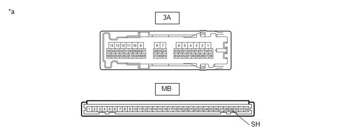
*a |
Component without wire harness connected (instrument panel junction block assembly) |
- |
- |
(b) Disconnect connector 3A from the instrument panel junction block assembly.
(c) Measure the resistance according to the value(s) in the table below.
Standard resistance:
Tester Connection | Condition | Specified Condition |
|---|---|---|
3A-20 - MB-29 (SH) |
Always |
Below 1 Ω |
| NG | |
REPLACE INSTRUMENT PANEL JUNCTION BLOCK ASSEMBLY |
|
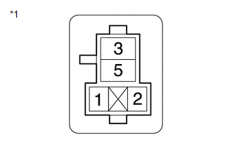
CHECK HARNESS AND CONNECTOR (BATTERY - S-HORN RELAY)
(a) Remove the S-HORN relay from the No. 4 relay block assembly.
(b) Measure the voltage according to the value(s) in the table below. Standard voltage:
|
|
| NG | |
REPAIR OR REPLACE HARNESS OR CONNECTOR |
|
CHECK HARNESS AND CONNECTOR (S-HORN RELAY - SECURITY HORN ASSEMBLY)
(a) Remove the S-HORN relay from the No. 4 relay block assembly.
(b) Disconnect connector A15 from the security horn assembly.
(c) Measure the resistance according to the value(s) in the table below. Standard resistance:
|
|
| NG | |
REPAIR OR REPLACE HARNESS OR CONNECTOR |
|
CHECK HARNESS AND CONNECTOR (S-HORN RELAY - INSTRUMENT PANEL JUNCTION BLOCK)
(a) Remove the S-HORN relay from the No. 4 relay block assembly.
(b) Disconnect connector 3A from the instrument panel junction block assembly.
(c) Measure the resistance according to the value(s) in the table below. Standard resistance:
|
|
| OK | |
REPLACE MAIN BODY ECU (MULTIPLEX NETWORK BODY ECU) |
| NG | |
REPAIR OR REPLACE HARNESS OR CONNECTOR |