Coolant pump
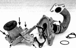
Coolant Pump
The three small arrows indicate the mounting bolt holes, and the two large arrows indicate the check holes.
Inspection
PROCEDURE
1. Failure of the coolant pump will cause serious damage due to engine overheating.
2. Warm up the engine before checking. With the engine running, pinch the upper radiator hose and gradually release it. If the pump is serviceable, fluid pressure should be felt in the hose.
* Do not place your hands close to the fan blades.
3. The pump has a check hole for fluid drainage. If the pump shaft seal fails, coolant will leak through the check hole (see Coolant Pump illustration). To locate the hole, illuminate the area behind the driven flange of the pump, directly below the shaft.
4. If the pump bearings fail, a howling noise will be heard at the front of the engine. Bearing wear can be determined by moving the pump up and down. A similar sound may be produced by a slipping drive belt, so the characteristic noise may lead to a wrong conclusion about pump failure. To rule out belt noise, spray a special drive belt compound onto the belt.
Removal
PROCEDURE
4E-FE Engine
1. Disconnect the battery negative cable and drain the coolant (see subsection 2.8.4).
2. Remove the alternator, referring to the description in subsection 3.3.11.
3. Remove the nut and two bolts securing the intake manifold stay at the rear of the engine, and remove the stay.
4. Disconnect the intake and bypass hoses from the intake pipe fitting at the rear of the engine. Remove the bolts securing the intake pipe from the pump, and remove the intake pipe. Remove the O-ring from the end of the pipe.
5. Remove the oil level gauge tube. Remove the bolt securing the oil level gauge tube and the alternator adjusting bracket to the engine, and pull the tube out of the oil pump housing.
6. Remove the bolts and two nuts securing the pump to the cylinder block, and remove the coolant pump assembly (the pulley may remain on the pump shaft).
7. Disassemble the pump and replace the gaskets. Thoroughly clean all mating surfaces of the pump to remove any remaining gasket material. Reassemble the pump using new gaskets.
4A-FE and 7A-FE Engines
8. Disconnect the battery negative cable and drain the coolant (see subsection 2.8.4).
9. Referring to the description in subsection 2.6.4, remove the power steering pump, alternator, water pump and air conditioning compressor drive belts. Then remove the upper power steering bracket.
10. Referring to the description, remove the cylinder head cover (see subsection 3.1.1.3) and the upper timing belt covers (see subsection 3.1.1.6).
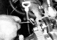
11. Remove the oil level gauge tube. Use a screwdriver to move the wiring harness clip away from the oil level gauge tube bracket. Remove the bolt securing the oil level gauge tube to the engine, and pull the tube out of the oil pump housing.
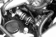
12. Remove the two nuts securing the right coolant pipe to the cylinder head, located behind the pump. Disconnect the connector from the coolant temperature sensor (indicated by the arrow) on the pipe.
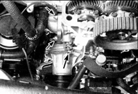
13. Working from above, remove the two nuts (small arrow) securing the pipe to the cylinder head, and remove the upper pump mounting bolt (large arrow).
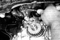
14. Working from below the vehicle, remove the two remaining pump mounting bolts from the cylinder block. Do not loosen the bolts securing the two pump covers until the pump assembly is fully removed from the cylinder block. Remove the coolant pump assembly with the pipe (the pulley may remain on the pump shaft).
15. Disassemble the pump (see Coolant Pump illustration) and replace the gaskets. Thoroughly clean all mating surfaces of the pump to remove any remaining gasket material, remove the O-ring and clean the groove. Reassemble the pump using new gaskets.
Installation
PROCEDURE
4E-FE Engine
1. Apply a bead of sealer (to be purchased from a dealer) approximately 3 mm wide to the seal groove in the pump housing, following the instructions supplied with the sealer.
2. Install the assembled pump to the cylinder block and secure with the bolt and two nuts.
3. Install the remaining components in the reverse order of removal. When installing the oil level gauge guide tube, replace the O-ring at the point where the tube enters the oil pump. Also replace the O-ring on the pump intake pipe.
4. After assembly, wait at least two hours for the sealer to set, then fill the cooling system with coolant (see Subsection 2.8.4), start the engine, and check for leaks and proper engine operation.
4A-FE and 7A-FE Engines
5. Install the assembled pump to the cylinder block, after replacing the O-ring. Replace the pump pipe gasket.
* If the pump is being replaced with a new one due to high mileage, also replace the hose connecting the pump pipe and the engine intake pipe.
6. Install the remaining components in the reverse order of removal. When installing the oil level gauge guide tube, replace the O-ring at the point where the tube enters the oil pump.
7. Fill the cooling system with coolant (see Subsection 2.8.4), start the engine, and check for leaks and proper engine operation.
Test yourself
A quick Toyota Corolla quiz: every answer comes with an explanation and a link to the manual page.