GENERAL INFORMATION
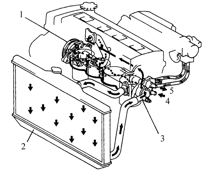
Cooling System Layout
1. Water pump
2. Radiator
3. Inlet hose
4. From heater
5. To heater

Heater Unit, Blower Unit and Air Conditioner Mounted Under the Instrument Panel 1. Air conditioner control panel
2. Air conditioner
3. Blower unit
4. Heater unit
Cooling System
The vehicles covered by this Manual use a forced-circulation, thermostatically controlled, pressurized cooling system (see figure Cooling System Layout).
Coolant circulation in the engine is provided by a centrifugal water pump mounted on the front of the cylinder block. Coolant flows around the cylinders and is directed to the rear of the engine. Then the coolant flows through the cast passages of the intake and exhaust manifolds, into the areas around the spark plugs and the exhaust valve guides.
The thermostat with a wax-pellet element is mounted next to the transaxle and covered by a cap. When the engine is warming up, the thermostat is closed and blocks the coolant flow to the radiator. After the engine reaches normal operating temperature, the thermostat opens, allowing coolant to flow to the radiator, where it is cooled and then returns to the engine.
The cooling system is connected to the atmosphere through the radiator cap, which contains a pressure relief valve. This design raises the boiling point of the coolant and improves cooling efficiency in the radiator. If the pressure in the cooling system exceeds the level at which the spring-loaded radiator cap valve opens, the valve lifts off its seat and part of the coolant flows through the overflow pipe into the coolant reservoir. When the system cools, excess coolant returns to the radiator.
The reservoir therefore maintains the coolant level in the system and also serves as a container for receiving overheated coolant.
This type of cooling system is called a closed system, because coolant discharged through the cap valve is retained for later use.
Heating System
The heating system consists of a blower fan and a heater core housed in a single case under the right side of the instrument panel, coolant hoses supplying and returning engine coolant, and the heating/air conditioning control panel located on the instrument panel (see figure Heater Unit, Blower Unit and Air Conditioner Mounted Under the Instrument Panel). Coolant heated by the engine flows through the heater core. The heating mode is selected by opening the air door, which connects the heater housing with the passenger compartment. The switch on the control panel controls the blower fan, which blows air across the heater core, heating the air.
Air Conditioning System
The air conditioning system consists of a condenser mounted in front of the radiator, an evaporator installed next to the heater core, a compressor mounted on the engine, a receiver-drier with a high-pressure reducing valve, and hoses and pipes connecting all these components.
The blower fan directs airflow from the passenger compartment across the evaporator core, where heat is transferred from the air to the refrigerant. Inside the evaporator, the refrigerant boils, forming low-pressure vapor, and heat is absorbed as the vapor leaves the evaporator. The compressor circulates the heated refrigerant, maintaining its high pressure, from the evaporator to the condenser, where the refrigerant is cooled, and back to the evaporator.
Test yourself
A quick Toyota Corolla quiz: every answer comes with an explanation and a link to the manual page.