Cooling Fan and Fan Relay
* Do not work in close proximity to the fan blades to avoid injury. The fan may start automatically!

Location of the engine main relay, air conditioning relay, and fan relays in the main relay block A. Air conditioning relay
B. Fan relay N3
C. Fan relay N2
D. Fan relay N1
E. Engine main relay
F. Fan circuit breaker
Inspection
PROCEDURE
1. If the fan does not switch off when the engine is cold, disconnect the wiring connector (indicated by the arrow) from the fan thermoswitch and remove the two nuts securing the thermostat housing cover to the housing (the upper nut is indicated). Now, when the ignition key is turned to the ON position, the fan should switch on.
2. If the fan does not switch on, check the fan relay, the wiring between the thermoswitch and the relay, and the fan motor itself.
3. The closed state of the thermoswitch contacts (indicated by the arrow), screwed into the thermostat housing cover, is checked with an ohmmeter. Disconnect the wiring connector and connect one ohmmeter probe to the terminal on the switch and the other probe to ground.
4. With the engine cold (coolant temperature below 82 °C), the ohmmeter should show a closed circuit. With the engine hot (coolant temperature above 93 °C), the ohmmeter should show an open circuit.
5. To determine the cause of fan motor failure (fan does not rotate with the engine hot or with the air conditioner on), check the fuses or fusible links (see subsection 12.1).
6. Then disconnect the connector on the fan motor (indicated by the arrow) and connect the fan motor directly to the battery using wires from the fusible link. If the fan does not rotate, replace the fan motor.
* Do not connect the test lead clips to each other, or touch them to any metal part of the vehicle.
7. If the previous test shows that the fan motor is serviceable, the relay, fuse or wiring is faulty. In this case, check the fan relay and the engine main relay using the procedure described below.
Relay Check
PROCEDURE
1. Locate the main junction block, which is on the left side of the engine compartment. On vehicles equipped with air conditioning, there is an auxiliary relay block located next to the battery (see figure: Location of the engine main relay, air conditioning relay and fan relay in the main relay block).

2. Remove fan relay N1 and use an ohmmeter to check the circuits between the terminals, following the figure. Vehicles are fitted with Nippondenso or Bosch relays, whose terminal numbering differs. Perform the relay check strictly in accordance with the figure.
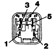
3. If the relay is serviceable, remove the engine main relay and check it in accordance with the figure. Between terminal pairs 3–5 and 2–4, the ohmmeter should show a closed circuit. Between terminals 1 and 2 there should be no closed circuit. If battery voltage is applied to terminals 3 and 5, there should be a closed circuit between terminals 1 and 2, and an open circuit between terminals 2 and 4.
4. If all tested relays are serviceable, take the vehicle to a dealer service department or a specialist workshop for diagnosis. Further independent testing is not recommended due to the complexity and variety of circuits used in the vehicle.
Replacement
PROCEDURE
1. Disconnect the battery from ground.
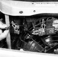
2. Disconnect the connector on the fan motor. The air conditioning fan is located in front of the radiator and is secured on the right side with a plastic push pin (indicated by the arrow). The right arrow indicates the fan connector.
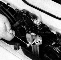
3. On the left side, the air conditioning fan is secured with two bolts: one bolt to the hood latch bracket (indicated by the arrow) and one bolt at the bottom. Access to the lower bolt is through the opening in the bumper.
* Vehicles with air conditioning have two fans. Fan N2 is installed in front of the radiator and provides additional cooling when the air conditioner is switched on. The procedure for checking this fan and its relay is exactly the same as for fan N1.
4. Drain part of the coolant to disconnect the upper radiator hose (see subsection 2.6.6), then disconnect the bypass hose at the top of the radiator.
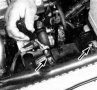
5. Remove the two lower mounting bolts, then the two upper mounting bolts (indicated by the arrows), and remove the shroud with the fan assembly from the vehicle by lifting it upward.

6. Holding the fan by the blades, remove the fan hub nut and the washer (if fitted). Remove the fan blade from the shaft.
* The fan blade of fan N2 (on vehicles with air conditioning) is secured with a cotter pin; there is no nut.

7. Remove the fan mounting bolts from the shroud. Remove the fan from the shroud.
8. Install the fan in the reverse order of removal.
Test yourself
A quick Toyota Corolla quiz: every answer comes with an explanation and a link to the manual page.