Inspection and Replacement of EFI System Components
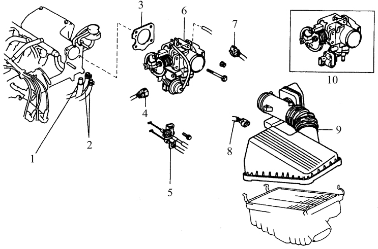
Throttle Body and Related Components 1. Air hose
2. Coolant bypass hoses
3. Gasket
4. Idle air control valve connector
5. Cable bracket
6. Throttle body
7. Throttle position sensor connector
8. Intake air temperature sensor connector
9. Air cleaner housing cover and air duct
10. California models only
THROTTLE BODY
Inspection
INSPECTION PROCEDURE
1. Make sure the throttle linkage moves smoothly.
2. Start the engine, disconnect the vacuum hose and use a vacuum gauge to make sure there is no vacuum at idle. Vacuum should be present in other engine operating modes.
Replacement
* Perform the work on a cold engine.
PROCEDURE
1. Drain the coolant from the cooling system (see subsection 2.8.4). Disconnect the battery negative cable (note that radio anti-theft codes will be erased).
2. Loosen the clamps and remove the air duct. Disconnect the throttle cable from the throttle lever (see subsection 5.10).
3. Remove the cable bracket (if equipped) and move it aside (do not remove the cable from the bracket).
4. If the vehicle is equipped with an automatic transmission, disconnect the throttle cable from the linkage (see subsection 7.2.4). Disconnect the cable brackets from the engine and move them aside.
5. Disconnect all vacuum hoses from the throttle body, making clear marks on them beforehand.
6. Disconnect the throttle position sensor connector.
7. Remove the four throttle body mounting bolts (indicated by arrows). On some engines, remove two bolts and two nuts.
8. Remove the throttle body and gasket from the intake manifold (see figure Throttle Body Assembly and Related Components).
9. Using a soft brush and carburetor cleaner, thoroughly clean all cast surfaces of the housing, then blow out all passages with compressed air.
* Do not clean the throttle position sensor with any cleaning agent. Carefully wipe the sensor with a clean, soft cloth.
Installation
PROCEDURE
1. Installation is performed in the reverse order of removal.
2. Tighten the throttle body bolts and nuts to the torque specified in subsection 5.1.
3. After completing the work, fill the cooling system with coolant (see subsection 2.8.4).
THROTTLE POSITION SENSOR
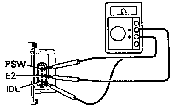
Throttle Position Sensor for 1.3 L Engines
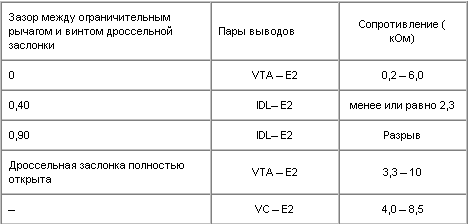
Throttle Position Sensor Inspection Table for 1.3 L Engines


Throttle Position Sensor for 1.6 and 1.8 L Engines
Throttle Position Sensor Inspection Table for 1.6 L and 1.8 L Engines
Inspection
PROCEDURE
1. Disconnect the throttle position sensor connector. On vehicles for California, apply vacuum to the throttle position sensor.
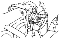
2. Insert a feeler gauge of the specified thickness between the throttle stop screw and the stopper.
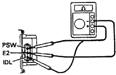
3. Using an ohmmeter, measure the resistance between the terminal pairs listed in the table, inserting feeler gauges of different thicknesses.
4. If the measured resistance differs from the value in the table, insert a 0.7 mm feeler gauge (for 1.6 L and 1.8 L engines) or 0.6 mm (for 1.3 L engines) between the throttle lever stopper and the throttle stop screw, and connect the ohmmeter to terminals IDL and E2. Loosen the sensor mounting screws and slowly turn the sensor clockwise until the ohmmeter shows an open circuit.
5. Tighten the screws, then use feeler gauges of the specified thickness to recheck continuity between the specified terminals.
Replacement
PROCEDURE
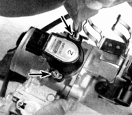
1. If the specified resistance cannot be obtained by adjustment, remove the sensor and replace it (screws are indicated by arrows).
2. Adjust in accordance with step 4.
FUEL PRESSURE REGULATOR
Inspection
See the description of the fuel pump and fuel pressure check procedure in subsection 5.3.
Replacement
PROCEDURE
1. Relieve the fuel system pressure (see subsection 5.2) and disconnect the battery negative cable (note that radio anti-theft codes will be erased).
2. Disconnect the vacuum hose from the regulator.
3. Place a metal container or pan under the fuel return hose.
4. On 1.3 L engines, unscrew the banjo bolt of the fuel return line, remove the washers, and disconnect the fuel return line from the fuel pressure regulator. On 1.6 and 1.8 L engines, loosen the clamp, slide the clamp back along the hose, and disconnect the fuel return hose from the fuel pressure regulator.
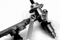
5. Remove the fuel pressure regulator mounting bolts and remove the regulator from the fuel rail.
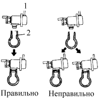
6. Replace the O-ring and make sure the fuel pressure regulator (1) is installed correctly on the fuel rail (2 – fuel line). If the regulator is installed at an angle, the seal will be compromised.
7. Installation is performed in the reverse order of removal. On 1.3 L engines, replace the copper washers on each side of the banjo fitting.
IDLE AIR CONTROL VALVE (FOR 1.6 AND 1.8 L ENGINES)
* The engine idle speed is set by the manufacturer and does not require adjustment under normal operating conditions. However, if the throttle body has been replaced or there is reason to suspect that the idle speed setting has changed (for example, the idle speed screw has been unscrewed from the throttle body), take the vehicle to a service station or specialized workshop.
Inspection
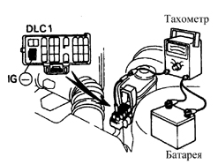
Connecting a Tachometer to the IG(–) Terminal of the Diagnostic Connector
PROCEDURE
1. Apply the parking brake, place the transmission shift lever in Neutral (manual transmission) or in Park (automatic transmission), chock the drive wheels. Connect a tachometer to the IG(–) terminal of the diagnostic connector (see figure Connecting the Tachometer to the IG(–) Terminal of the Diagnostic Connector). Start the engine and warm it up to normal operating temperature. Read the idle speed and compare it with the specification in subsection 5.1.
2. Using a jumper wire, short terminals TE1 and E1 of the diagnostic connector.
3. The idle speed should increase from 1000 rpm to 1200 rpm within 5 seconds, then decrease to the initial value. If the idle speed increases and decreases as described above, the valve is serviceable. If the engine behaves differently, check the resistance of the air control valve.
4. Remove the jumper wire.
5. Disconnect the valve connector.
6. Measure the resistance between the center terminal and each of the other two terminals. Compare the valve resistance with the value specified in subsection 5.1. If the resistance is within specification, the valve is serviceable and the wiring or control module should be checked. If the resistance differs from the specification, replace the valve.
7. Reconnect the disconnected connector to the valve.
Replacement
PROCEDURE
1. Remove the throttle body.
* Access to the control air valve is limited, so it is recommended to remove the throttle body to ensure correct installation of the new valve.
2. Unscrew the screws and remove the valve with the gasket.
3. Install the valve in the reverse order of removal. Before installation, replace the valve gasket.
FUEL DISTRIBUTOR AND INJECTORS
Inspection
Perform the fuel injection system checks (see subsection 5.11).
Replacement
PROCEDURE
1. Relieve the fuel system pressure (see subsection 5.2).
2. Disconnect the battery ground cable.
3. Disconnect the crankcase ventilation hose from the cylinder head and intake manifold.
4. On 1.8 L engines, remove the intake manifold cover (see items 1–10 below).
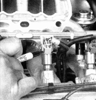
5. Mark each injector connector clearly. Disconnect the connectors from the injectors and move the wiring aside. On 1.3 L engines, remove the bolt and disconnect the wiring from the mixture chamber bracket. Remove the nut and bolt and remove the bracket.
6. Disconnect the vacuum probe hose from the fuel distributor.
7. Disconnect the fuel hoses from the pressure regulator and the fuel distributor.

8. Remove the fuel distributor mounting bolts (indicated by arrows).

9. Remove the fuel distributor with the injectors.
10. Remove the injectors from the distributor and place them in a box with individual marking.
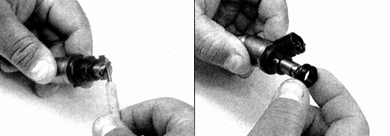
11. If the injectors are not to be replaced, replace the O-rings (photo left) and seals (photo right).
12. Install the injectors in the reverse order of removal.
13. Tighten the fuel distributor mounting bolts to the torque specified in subsection 5.1.
IDLE SPEED COMPENSATION VALVE WITH AIR CONDITIONER ON
Inspection
PROCEDURE
1. Apply the parking brake, place the transmission shift lever in Neutral (manual transmission) or in Park (automatic transmission), chock the drive wheels. Connect a tachometer to the IG(–) terminal of the diagnostic connector (see figure Connecting the Tachometer to the IG(–) Terminal of the Diagnostic Connector). Start the engine and warm it up until normal operating temperature and idle speed are reached. Turn on the air conditioner.
2. Using a jumper wire, short terminals TE1 and E1 of the diagnostic connector.
3. The idle speed should increase from 1000 rpm to 1200 rpm within 3 seconds after shorting the terminals, then decrease to the initial value. After 15 seconds, check the idle speed again; it should be approximately 100 rpm higher than the normal value. If the idle speed changes as described above, the valve is serviceable. If the speed increases by more than 100 rpm, adjust the idle speed range by turning the adjusting screw. If the engine speed does not change or decreases, check the resistance of the compensation valve.
4. Remove the jumper wire.
5. Disconnect the connector from the valve.
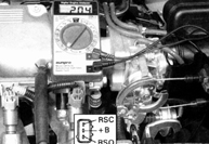
6. Measure the resistance between the terminals. The resistance should be within 30–34 Ohm. If the resistance is within specification, the valve is serviceable and the wiring or control module should be checked. If the resistance differs from the specification, replace the valve (see below).
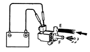
7. Apply battery voltage to the terminals and verify that air flows from passage E to passage F.
* Passage E is located at the top, and passage F is at the bottom.
8. Remove the voltage and verify that air does not flow from passage E to passage F.
9. If the test results are unsatisfactory, replace the valve.
Replacement
PROCEDURE
1. Unscrew the mounting screws and remove the valve with the gasket.
2. Install the valve in the reverse order of removal.
3. Replace the gasket before installing the valve.
INTAKE MANIFOLD MIXTURE CHAMBER COVER (FOR 1.6 AND 1.8 L ENGINES)
Removal
* Perform the work on a cold engine.
PROCEDURE
1. Disconnect the battery ground cable.
2. Disconnect the connectors from the compensation valve, throttle position sensor, and the solenoid of the recirculation and fuel vapor recovery systems.
3. Disconnect the throttle cable (see subsection 5.10) and the transmission linkage (see subsection 7.2.4) from the throttle body.
4. Disconnect the throttle cable from the intake manifold (see subsection 5.10).
5. Mark and disconnect the vacuum hoses from the mixture chamber cover, the recirculation valve (if equipped), and the fuel pressure regulator.
6. Disconnect the crankcase ventilation hose from the mixture chamber cover.
7. Remove the bolt and the bracket (if equipped).
8. Disconnect the coolant hoses from the throttle body. Plug the hoses.
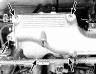
9. Remove the intake manifold cover bolts (indicated by arrows) and the lower (side) bolts.
10. Remove the surge tank cover assembly with the throttle body from the lower intake manifold.
Installation
PROCEDURE
1. Clean and inspect the mating surfaces of the lower intake manifold (see subsection 3.1.1.4) and the surge tank.
2. Replace the lower intake manifold gasket.
3. Install the surge tank cover assembly with the throttle body onto the intake manifold.
4. Make sure the gasket is installed correctly.
5. Install the mounting bolts to the intake manifold and tighten them to the torque specified in subsection 3.1.1.1.
6. Installation is the reverse of removal.
PURGE CONTROL VALVE (1.3L ENGINE)
Inspection
PROCEDURE
1. Disconnect the connector from the purge control valve. The valve is located on the back side of the intake manifold.
2. Measure the resistance between the valve terminals. Resistance must be within 30–33 Ohms. If the resistance is normal, the valve is serviceable. If the resistance differs from the specification, replace the valve.
3. Blow air through the valve from the diaphragm side and make sure air does not pass through the lower fitting.
4. Apply battery voltage to the terminals and make sure air flows out of port F.
5. If the test results are unsatisfactory, replace the valve.
Replacement
PROCEDURE
1. Remove the mounting screws and remove the valve with the gasket.
2. Install the valve in the reverse order of removal.
Test yourself
A quick Toyota Corolla quiz: every answer comes with an explanation and a link to the manual page.