Fuel Pump and Fuel Pressure
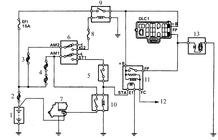
Fuel Pump Power Supply Circuit 1. Battery
2. Main fuse (3.0 W)
3. AM1 fusible link, 30 A
4. AM1 fusible link, 40 A
5. Starter auxiliary relay switch (on vehicles with manual transmission) or Park/Neutral switch
(on vehicles with automatic transmission)
6. Ignition switch
7. Starter
8. Ignition fuse (10 A)
9. Main EFI relay
10. Starter auxiliary relay
11. Fuel pump relay
12. To control unit
13. Fuel pump
Fuel Pump Inspection
PROCEDURE
1. Turn the ignition switch on (do not start the engine).
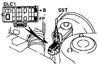
2. On all vehicles manufactured in 1993-1994, as well as vehicles with a 1.3 and 1.6 L engine manufactured from 1995, short terminals B+ and FP (arrow) on the diagnostic connector using a special jumper wire (SST – special service tool).
* On vehicles manufactured from 1995 with a 1.8 L engine, and on all vehicles equipped with the OBD II on-board diagnostic system, power is not supplied to the fuel pump through the diagnostic connector. On these vehicles, start the engine to read the fuel pressure.
3. After jumping these terminals, voltage is supplied to the fuel pump. You should hear the pump operating in the area under the rear seat, and fuel pressure should be present in the hose from the fuel filter.
4. Remove the jumper wire. Install the cap on the diagnostic connector.
5. Turn the ignition switch off.
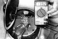
6. If the pump does not operate, check the following circuit components: the 15 A fuse for the main EFI relay, the 30 A ignition key fusible link (AM2 link, see the Fuel Pump Power Supply Circuit figure), the main EFI relay and the fuel pump relay, the fuel pump, as well as the wiring and connectors (see the electrical circuit diagram at the end of this manual).
Fuel Pump Inspection
To perform the procedure described below, you will need a fuel pressure gauge with a hose rated for at least 3 kgf/cm². The hose end must be of the banjo type, i.e., sealed by a bolt with an internal through passage (Toyota special service tool 09268–45012).
If a special pressure gauge is not available, proceed as follows.
PROCEDURE
1. Obtain a ready-made banjo-type fitting with an internal diameter of 12 mm that matches the hose and clamp of your pressure gauge.
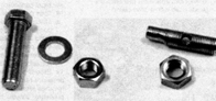
2. If a suitable fitting of the correct diameter is not available, obtain an M12 x 1.25 mm bolt, grind off the bolt head, and drill two holes: one through the center of the bolt lengthwise, and another across the center of the bolt, intersecting the longitudinal hole. Install the nut and locknut, sealing the threads with PTFE tape.
3. Remove the fuel filler cap to release residual pressure in the tank.
4. Make sure the battery voltage is at least 12 V (refer to subsection 3.3.10).
5. Perform the fuel system depressurization procedure (refer to subsection 5.2).
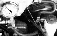
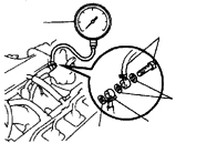
6. Fuel pressure can be checked in two places. If the special adapter (Special Service Tool 09268-45012), which installs on the fuel distributor, is available, remove the bolt from the fuel distributor and install the pressure gauge adapter (illustration on the left). If you have made an adapter yourself in the form of a drilled bolt with a locknut, remove the fuel filter cover and install the homemade gauge fitting in place of the cover bolt (photo on the right).
7. Connect the pressure gauge in the following order. If a standard gauge is used, connect it to the special adapter installed on the fuel distributor. Be sure to install new gaskets on both sides of the adapter. If a homemade adapter in the form of an M12 x 1.25 bolt is used, screw the bolt into the fuel filter, tighten the locknut, and connect the gauge hose with a clamp.
8. Place the automatic transmission selector lever in the Park position, or place the manual transmission shift lever in Neutral (if the vehicle is equipped with a manual transmission).
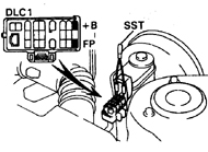
9. On all vehicles manufactured in 1993-1994, and on vehicles with a 1.3 and 1.6 L engine manufactured from 1995, jumper terminals B+ and FP on the diagnostic connector together using a special jumper wire (SST).
* On vehicles manufactured from 1995 with a 1.8 L engine, and on all vehicles equipped with the OBD II on-board diagnostic system, power supply to the fuel pump through the diagnostic connector is not provided. On these vehicles, start the engine to read the fuel pressure.
10. Turn the ignition on (do not start the engine). Read the gauge value.
11. If the pressure is high, check the fuel return line. If fuel flows through the return line, replace the fuel pressure regulator; if the pressure is low, pinch off the fuel return line.
12. If the pressure increases, replace the fuel pressure regulator. If the pressure does not increase, check the fuel supply line, the fuel pump and the fuel filter.
13. Remove the jumper from the diagnostic connector or from the fuel pump connector.
14. Start the engine.
15. Check the fuel pressure at idle and compare the result with the specification.
16. If the pressure differs from the specification, check the vacuum hose and the fuel pressure regulator.
17. Stop the engine and make sure the fuel pressure is maintained at 1.35 kgf/cm² for 5 minutes after shutdown. If the pressure drops faster, the cause may be a leak in the fuel pump, the pressure regulator or an injector.
Fuel Pressure Regulator Inspection
PROCEDURE
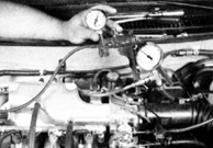
1. Disconnect and plug the vacuum hose of the fuel pressure regulator. Connect a hand-operated vacuum pump to the regulator. Start the engine and read the fuel pressure with no vacuum applied to the regulator. Apply vacuum to the regulator and read the fuel pressure again. As vacuum increases, fuel pressure should decrease. Compare the fuel pressure readings with the values given in Subsection 5.1.
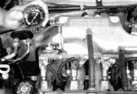
2. Connect the vacuum hose to the regulator and check the fuel pressure at idle. Compare the fuel pressure readings with the values given in Subsection 5.1. Disconnect the hose and read the pressure again; as soon as the hose is disconnected, the pressure should jump up to the upper specification limit.
3. If the fuel pressure at idle with the hose disconnected is too high, measure the vacuum in the vacuum hose with a vacuum gauge. If the vacuum gauge shows no reading, check the intake manifold and the mixing chamber (cover) of the manifold for leaks.
4. If the fuel pressure is low, firmly pinch off the fuel return line and read the fuel pressure. If the pressure does not increase, the fuel pump is faulty or the fuel supply line is clogged. If the pressure rises sharply, replace the fuel pressure regulator (see Subsection 5.12).
5. If the fuel pressure is too high, perform the system depressurization procedure (see Subsection 5.2), disconnect the fuel return line and blow it out. If the fuel return line is not clogged, replace the pressure regulator.
6. If the pressure behavior differs from that described in step 2, replace the pressure regulator (see Subsection 5.12).
7. Carefully remove the pressure gauge, placing a rag under the connection being disconnected.
8. Install the fuel distributor fitting, after replacing the gaskets.
9. Wipe up spilled fuel.
10. Start the engine and check for fuel leaks.
Main Relay System Inspection
PROCEDURE
1. Two relays are included in the fuel system electrical circuit. First check for battery voltage at the main relay, then at the fuel pump relay.

2. Disconnect the main relay from the connector, then turn the ignition on (do not start the engine) and check for battery voltage.
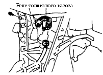
3. If battery voltage is present, reinstall the main relay and check for battery voltage at the fuel pump relay. To access the relay, the receiver must be removed (see Subsection 12.11).
4. If battery voltage is present at both relays, inspect the relays themselves.
Main Relay Inspection (Nippondenso Type)
PROCEDURE

1. Using an ohmmeter, check for continuity between terminals 1 and 2. Between terminals 3 and 5 the ohmmeter should show an open circuit.
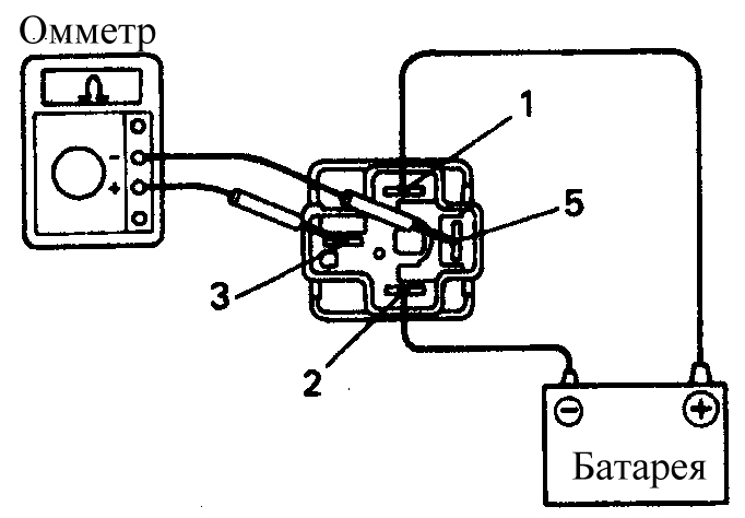
2. Apply battery voltage to terminals 1 and 2. Now there should be continuity between terminals 3 and 5. If the test results differ, replace the relay.
Main Relay Inspection (Bosch Type)
PROCEDURE

1. Using an ohmmeter, check for continuity between terminals 86 and 85. Between terminals 87 and 30 the ohmmeter should show an open circuit.
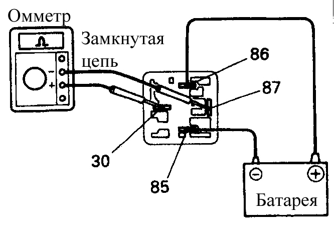
2. Apply battery voltage to terminals 86 and 85. Now there should be continuity between terminals 87 and 30. If the test results differ, replace the relay.
Fuel Pump Inspection
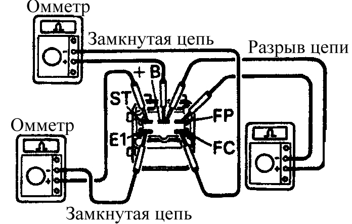
1. Using an ohmmeter, check continuity between terminals ST and E1. Check continuity between terminals +B and FC. There should be no continuity between terminals +B and FP.

2. Apply battery voltage to terminals ST and E1. Now there should be continuity between terminals +B and FP. If the test results differ, replace the relay.
Test yourself
A quick Toyota Corolla quiz: every answer comes with an explanation and a link to the manual page.