Electronic Fuel Injection System (EFI System)
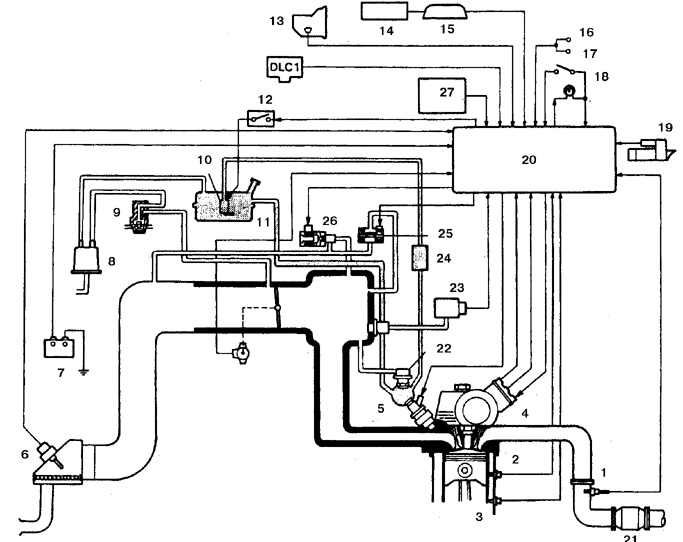
Electronic Fuel Injection (EFI) System for 1.6 and 1.8 L engines (engines 1.3 L are equipped with a similar system)
1. Oxygen sensor
2. Engine coolant temperature sensor
3. Knock sensor (only for engines 1.8 L 7A-FE)
4. Integrated electronic ignition unit (IIA)
5. Fuel injector
6. Intake air temperature sensor
7. Battery
8. Evaporative emission canister
9. Vacuum valve (distributor)
10. Fuel pump
11. Fuel tank
12. Fuel pump relay
13. Park/Neutral position switch (for vehicles with automatic transmission)
14. Vehicle speed sensor
15. Instrument cluster
16. Headlight relay
17. Rear window defroster switch
18. Stop light switch
19. Starter
20. Electronic control unit (ECU)
21. Catalytic converter
22. Fuel pressure regulator
23. Manifold absolute pressure sensor
24. Fuel filter
25. Idle air control valve
26. Throttle position sensor
27. Air conditioning amplifier
The vehicle is equipped with an electronic fuel injection (EFI) system, which consists of three subsystems: the fuel system, the air intake system, and the electronic control system.
FUEL SYSTEM
The fuel pump, located in the tank, supplies fuel at constant pressure to the fuel rail, from which fuel is evenly distributed to the injectors. From the fuel rail, fuel is injected into the intake ports of the cylinders through the injectors. The amount of injected fuel is strictly controlled by the electronic control unit (ECM). The fuel pressure regulator maintains fuel pressure in accordance with the vacuum in the intake manifold. The fuel filter is installed between the fuel pump and the fuel rail and is designed to clean the gasoline and protect the injection system components from failure.
AIR INTAKE SYSTEM
The air intake system consists of the air filter, the throttle body and the duct connecting these two components. The intake air temperature sensor (IAT sensor) monitors the temperature of the intake air. The signal from the sensor is sent to the electronic control unit, which controls the amount of injected fuel in accordance with the air temperature. The throttle valve is controlled by the driver. As the throttle valve opens, the speed of the incoming air increases, which causes its temperature to decrease. The sensor detects the change in air temperature and sends a signal to the ECM, which in turn sends a signal to the injectors to increase the amount of injected fuel.
ELECTRONIC CONTROL MODULE (ECM)
Electronic fuel injection and other systems are controlled by the electronic control module, which in turn is part of the central computer control system (CCS system). The ECM contains a microprocessor.
The control module receives signals from a number of sensors that monitor such parameters as intake air temperature, throttle position angle, engine coolant temperature, engine speed, vehicle speed and oxygen content in the exhaust gases.
Based on this data, the control module determines the fuel injection duration, which maintains the optimal air-fuel ratio in the mixture. Some of these sensors and the corresponding relays actuated by the control module are not part of the electronic fuel injection system, but are installed throughout the engine compartment.
Subsection 6.2 provides a more detailed description of the control module and the engine electrical systems controlled by this module.
Inspection
INSPECTION PROCEDURE
1. Check all ground connections for security. Check the system wiring and connectors. Loose electrical connections and poor ground contact can cause many malfunctions that appear as serious failures.
2. Check the state of charge of the battery. Normal operation of the sensors and fuel metering actuators depends on the supply voltage.
3. Check the condition of the air filter. A clogged filter element can cause a significant deterioration of performance, including fuel economy (see subsection 2.7.2).
4. If a blown fuse is found, replace it and check the operation of the corresponding circuit. If the fuse blows again, locate the wire shorted to ground in the wiring.
5. Check the air duct from the filter to the intake manifold for leaks. Air leakage into the intake duct causes excessively lean mixture. Also check the condition of the vacuum hoses connected to the intake manifold.
6. Remove the air duct from the throttle body and check for carbon and resin deposits. If contaminated, clean the body with aerosol carburetor cleaner and brush with a toothbrush (first make sure, by reading the instructions on the can, that the cleaner is safe for oxygen sensors and the catalytic converter).
7. With the engine running, place a stethoscope against each injector and listen for the characteristic clicks indicating normal injector operation.
8. If no stethoscope is available, use a long screwdriver. Place the tip of the screwdriver against the injector and hold your ear close to the handle.
9. If the listening test gives doubtful results, purchase a special injector test light and plug it into the injector connector. Start the engine and make sure the light flashes at each injector connector. This verifies the voltage supplied to the injectors.
10. With the engine off, disconnect the injector connectors and check the resistance of each injector. Resistance of each injector should be within 13.4–14.2 ohms. If the resistance differs, replace the injector.
11. Other checks should be performed at an authorized service center or specialized workshop, since the malfunction may be caused by a faulty control module.
Test yourself
A quick Toyota Corolla quiz: every answer comes with an explanation and a link to the manual page.