Doors
A feature of the Audi 80 is doors consisting of two parts. The inner part, the door frame for mounting the mechanisms, is attached to the outer part, the main door element, with four bolts. Because of this, in the event of minor damage from a collision, the outer part can be replaced without spending time transferring the window regulator mechanisms and unlocking.
Care of the Door Seals
The outer door seals on the Audi 80 require special care, because seals with cracks are not only not airtight but also cause loud noise from airflow while driving. The best care product for the seals is deer tallow. It also has another useful effect: in winter it prevents the seals from freezing to the body.
Door Removal
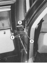
Door hinge bolts – illustration shows the rear door:
1 – door mounting bolts;
2 and 3 – adjustment bolts.
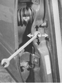
The striker bolt can be adjusted in all directions (arrows) to ensure the door closes properly.
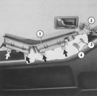
The upper element of the door armrest (1) on 4- and 5-cylinder models – version without switch – is secured to the trim panel at four points. The rear view mirror adjustment mechanism (2) has been removed, and the adjusting knobs (3 and 4) have been disconnected.
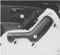
This illustration shows removal of the armrest (2) on the 6-cylinder model. A total of three internal hex bolts must be removed, after which the armrest can be lifted off the retainers. Carefully remove the switch block (1) from the mount.
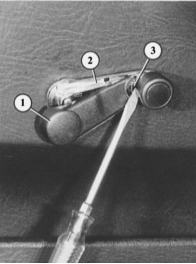
The window regulator handle panel (1) can be removed after pressing the retaining tab (3) on the window regulator handle (2).
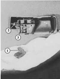
Before removing the door trim panel, remove the foam seal (1) from the back of the door opening mechanism. Then remove the bracket (2) and disconnect the cable end (3).
PROCEDURE
On models with speakers, power adjustment or power windows installed in the doors, remove the door trim panel to disconnect the electrical connectors. The procedure is described in the following section. The same applies to the wiring and hoses of the central locking system.
Remove two hex bolts each from the upper and lower hinges and remove the door. The hinges remain on the body.
After installation, align the new door (see the following section).
Correct Door Installation
PROCEDURE
For installation and adjustment of the door, the vehicle must stand level on all four wheels. If the vehicle is raised, the body may distort slightly, which will ultimately cause the door to be misaligned.
Adjust according to the following criteria:
the gap width at the front and rear edges of the doors must be 5–6.5 mm. If not, reposition the doors.
The body contour must be matched: check around the entire perimeter whether the beltline at door handle height is straight, without steps, and whether the door is installed too low or too high.
Attention must be paid to noise insulation. This is achieved by correct door installation: the front edge of the rear doors overlaps the center pillar. At this point, measure the pillar/door distance with the door closed. It must be 14.5 mm. Based on this gap, the other door edges are set: the front edge of the front door must be recessed 0.5–1 mm relative to the front fender. The rear edge of the front door must protrude 0.5–1 mm beyond the front edge of the rear door. And the rear edge of the rear door must protrude the same distance beyond the rear fender.
Door Alignment
PROCEDURE
Horizontal adjustment for door gap: loosen the rear bolt on the hinge-to-body connection, then slightly loosen the threaded bushing located behind it.
Slightly loosen the front bolt on the hinge-to-body connection so the door can be moved.
Close the door and set the door gap.
Carefully open the door and tighten the front hinge bolts.
Screw in the threaded bushing until it seats, then tighten the rear bolt.
Vertical adjustment (contour): loosen the bolts between the hinge and body (as previously done), and move the door up or down.
Retighten the bolts.
Lateral adjustment, front edge of door (noise insulation): loosen the bolts between the hinge and door frame.
Close the door and move it within the door opening to the specified dimensions.
Open the door and tighten the bolts.
Lateral adjustment, rear edge of door (noise insulation): slightly loosen the striker bolt that engages the door latch.
Close the door and move it within the door opening to the specified dimensions.
Open the door and tighten the striker bolt.
From inside the vehicle, check that the door contacts the rubber seals evenly.
Window frame installation: once the main door element is correctly adjusted, check the position of the window frame in the door cutout. The outer door seal must not protrude beyond the roof rail.
If adjustment is required, remove the door trim panel and loosen the four window frame mounting bolts.
Close the door.
Ask an assistant to press the frame into the door cutout. It is better to press slightly harder, as the rubber will absorb the shock.
If the installation is correct, tighten the bolts from the inside (upper bolts first). Tightening torque: 20 N·m.
Removal of Door Trim Panel
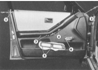
Screws to be removed for door trim panel removal
1, 2 – upper end screws;
3, 4 – armrest upper panel mounting screws;
5 – armrest lower panel screws;
6 – window regulator handle screw; the screw in the door opening mechanism is not visible.
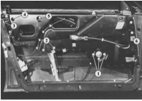
With the door trim panel removed, the following become visible:
1 – window regulator drive mechanism screws;
2, 5 – guide rail screws;
3, 6 – threaded connections of both door components.
4 – door handle mounting screw.
The front door trim panel removal procedure is described below. The rear door trim panel is removed in exactly the same way.
PROCEDURE
Removal of window regulator handle: insert a screwdriver under the decorative cover near the handle shaft and press the retaining tab. Remove the cover toward the shaft. Remove the Phillips-head bolts located under it.
Models with 4- and 5-cylinder engines: driver door with switches in the trim panel: remove the switches (refer to Switches).
Front doors without switches: remove the two Phillips-head screws and remove the lower armrest insert.
Access to the four screws securing the upper element is now available. Remove the screws.
Pull out (upward) both knurled wheels of the rear view mirror adjustment button (manual mirror adjustment). If necessary, use a screwdriver to assist.
Pull the upper insert toward the rear edge of the door with force and release the clips on the front edge of the door (this is very difficult).
Now pull the insert upward.
Lift the plastic retaining clips of the removed insert slightly and remove the rear view mirror adjustment mechanism downward.
Models with 6-cylinder engine: loosen the three 4 mm hex socket screws on the underside of the armrest.
Remove the armrest and disconnect the switches.
Unscrew the armrest bracket.
All models: inside the door opening mechanism, pull the opening lever and insert a screwdriver into the hole in the door opening mechanism cup. Remove the Phillips-head screw.
Pull the door opening mechanism cup forward and remove it from the retainers.
On the back of the door opening mechanism, remove the bracket and disconnect the cable.
Remove one Phillips-head screw each at the rear and front on the outer side of the door trim panel.
Remove the rubber seals at the front and rear of the window frame trim.
The interior door lock button remains installed.
Now lightly tap the bottom of the door trim panel with the edge of your palm (heel of the thumb) to lift it upward and disengage the clips on the back of the trim panel from the door frame.
Remove the trim panel.
Before installation, insert the rubber grommets into the mounting holes on the door frame.
To make it easier to insert the fasteners, lubricate the grommets with petroleum jelly or silicone paste.
During installation, make sure the interior door lock button engages correctly in the hole in the trim panel.
If a new door or new trim panel is installed, the trim panel installation position can be adjusted: turn the adjusting screw at the top on the inner side of the door in or out. The correct position: the screw head must be 21 mm below the window seal strip located opposite it.
Removal of Outer Door Panel
After minor damage to the outer door panel, it may be necessary to separate the outer door panel from the door beam assembly. In this case, it is recommended to paint the new outer door panel before installation. However, work must be performed with particular care.
PROCEDURE
Remove the door trim panel.
Remove the door and place it outer side down on a soft pad (foam rubber, warm blankets).
Disengage the door opening mechanism cable from the retaining clips toward the lock.
Remove the 4 mounting screws on the end faces of the door (refer to the illustration above).
Lift the outer door panel upward to remove it.
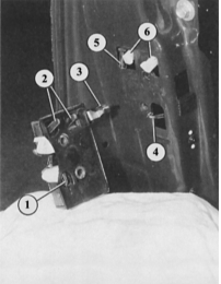
Removal of Door Lock
1 – lever for door opening cable (4);
2 – lever for interior door locking mechanism (6);
3 – lever for outer door handle drive rod (5).

Outer Door Handle, Disassembled
1 – front mounting screw with star key;
2 – door opening mechanism drive rod;
3 – door handle;
4 – lock plate;
5 – door locking mechanism drive rod.
PROCEDURE
Remove the two 6 mm hex socket screws.
Pull the lock slightly rearward. The connected cables and drive rods will become visible.
Disconnect the cables and rods from the inside of the door opening mechanism and the door locking mechanism.
To disconnect the drive rods from the outer door handle, turn the lock 90°.
For lock installation, remove the inner trim panel to allow better access to the drives.
To remove the interior door opening mechanism cable, move the lock lever aside with a screwdriver and hold it.
Removal of Outer Door Handle
PROCEDURE
Remove the inner door trim panel.
Through the opening on the inner side of the door, remove the T25 star-head screw (purchase the appropriate key).
At the level of the lock cylinder, feel through the door frame for the small latch and turn it 65° toward the rear edge of the door.
Now the door handle can be removed inward.
Remove the lock cylinder and outer plate outward. Turn the plate slightly while doing so.
Disconnect the drive lever from the door lock.
Removal of Lock Cylinder
PROCEDURE
Remove the outer door handle.
Insert the key into the lock cylinder so that the locking plates and springs do not fall out when the cylinder is removed.
Remove the retaining ring at the rear end of the lock cylinder.
Remove the catch and the elastic element, noting their position for reinstallation.
Remove the lock cylinder from the bracket by pushing it forward.
Apply insulating and rust-removing spray to the new lock cylinder.
Removal of Window Regulator
PROCEDURE
Remove the door trim panel.
Disconnect the built-in door element box. The outer door panel remains connected to the vehicle.
Pry off the retaining clip of the window regulator and glass. Remove the spacer washers and disconnect the glass.
Remove the drive and window regulator mounting screws; on the electric window regulator, loosen the nuts instead of the screws.
The window regulator and drive mechanism or the window regulator motor form a single unit and can only be removed or replaced as a complete assembly.
Removal of Door Glass
PROCEDURE
Remove the window regulator mechanism (refer to the previous section).
Remove the plugs from the window guide.
Pull the glass out of the window guide downward.
After installing the glass, insert the plug into the guide from below. The distance between the lower edge of the plug and the lower edge of the glass guide must be 25 mm.
Reinstall the window regulator.
Moldings
The door moldings are glued on. For removal and installation, refer to the procedures earlier in this chapter.
Test yourself
A quick Audi 80 quiz: every answer comes with an explanation and a link to the manual page.