compressor
Description and Operation
Description
The compressor is the drive unit of the air conditioning system.
It is located on the side of the cylinder block and is driven by the engine via a poly-V belt.
The compressor converts low-pressure, lower-temperature gaseous refrigerant into high-pressure, high-temperature gaseous refrigerant.
Variable Displacement Swash Plate Compressor
The compressor has a swash plate that rotates, pushing the pistons back and forth, which in turn compress the refrigerant.
The variable displacement swash plate compressor changes the swash plate angle to change the refrigerant discharge volume. It allows precise control of cooling capacity according to cabin and driving conditions.
The internal control variable displacement compressor changes the swash plate angle according to the suction pressure using the MCV (mechanical control valve).
The external control variable displacement compressor changes the swash plate angle according to the ECV (electronic control valve) signal from the heating and air conditioning control unit.
This provides stable temperature control and improves driving comfort.
ECV Control Circuit
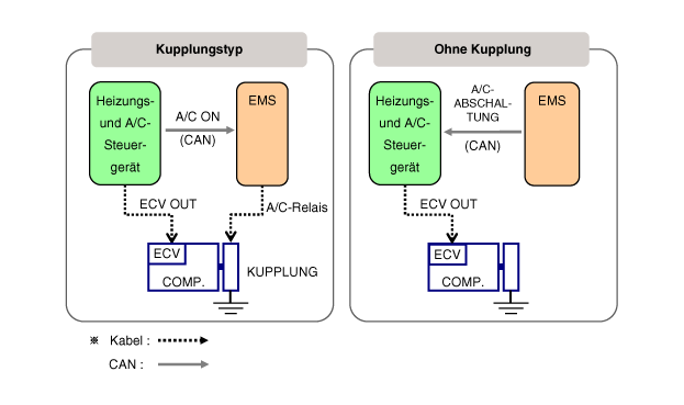
Components and Components Location
COMPONENT LOCATION
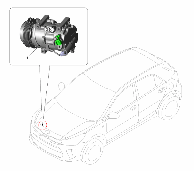
| 1. Compressor |
COMPONENTS LOCATION
[U2 engine]
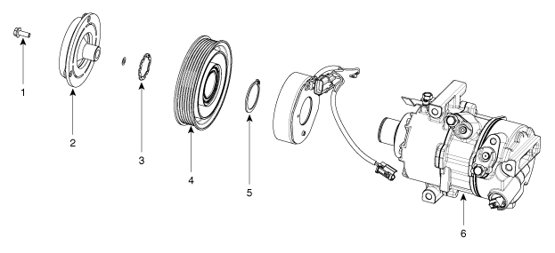
| 1. Clutch Screw 2. Limiter and Hub Assembly 3. Snap Ring |
4. Pulley 5. Snap Ring 6. Compressor Assembly |
[Kappa Engine]
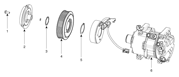
| 1. Clutch Screw 2. Limiter and Hub Assembly 3. Snap Ring |
4. Pulley 5. Snap Ring 6. Compressor Assembly |
repair procedures
expansion
If the compressor operates only slightly, start the engine and let it run and turn on the air conditioner for a few minutes. Then stop the engine.
Disconnect the battery ground cable.
Discharge the refrigerant at a service station.
Loosen the drive belt.
D 1.6 U2 TCI (refer to Engine Mechanical – Drive Belt)
G 1.0 T-GDI KAPPA (refer to Engine Mechanical – Drive Belt)
G 1.2 MPI KAPPA (refer to Engine Mechanical – Drive Belt)
G 1.4 MPI KAPPA (refer to Engine Mechanical – Drive Belt)
Disconnect the suction line (A) and discharge line (B) from the compressor.
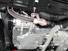
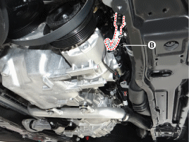
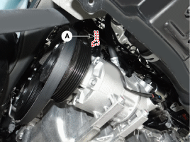
Disconnect the compressor switch connector (A).
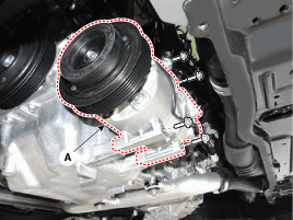
Loosen the mounting bolts and remove the compressor (A).
Tightening torque: 20.0 – 33 N·m
Installation
Check the length of the compressor mounting bolts, then tighten them in the specified sequence.
Tightening torque: 20.0 – 33 N·m
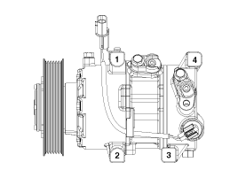
Installation is the reverse of removal.
Discharge all refrigerant. When installing a new compressor, drain the oil from the removed compressor and measure the volume. Drain the same amount of oil from the new compressor (through the suction port) as was drained from the original compressor (120 cm3).
Replace the O-rings on all connections with new ones and apply a small amount of compressor oil to the O-rings during assembly. Make sure to use the correct O-rings for R-134a refrigerant to prevent leaks.
To avoid contamination, do not add compressor oil from an opened container and never mix it with other compressor oils.
Immediately after removing the oil, reseal the container cap to prevent moisture from entering the container.
TEST
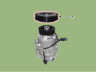
Inspect the clutch disc and hub friction surface (A) for discoloration, peeling, and other damage. If damaged, replace the entire clutch assembly.
Check the bearing play and pulley (B) resistance by turning the pulley by hand. Replace the clutch assembly if excessive play is present, or if resistance or excessive noise is felt when turning.
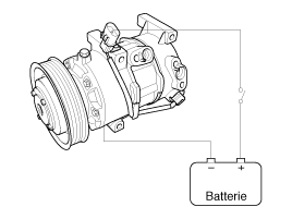
Check the operation of the magnetic clutch.
Connect the compressor terminal to the battery positive (+) terminal and connect the battery negative (-) terminal to the compressor body. Check the magnetic clutch operating noise to check its condition.
External Control Valve Compressor Inspection (KDS)
Compressor type: fixed displacement compressor, external control valve, internal control valve.
On the fixed displacement type and the type with an internal control valve, the compressor can be checked by listening for the clutch operating noise.
However, with an external control valve, this check may not be possible because the clutch cannot be checked this way.
Therefore, for the ECV type, it must be checked using the KDS as described below.
Connect the KDS to the vehicle and select "A/C Compressor Test (ECV Type)".
[ECV1]
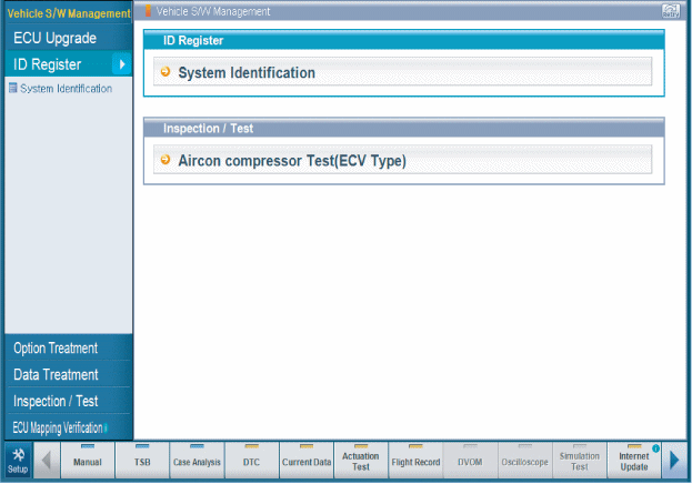
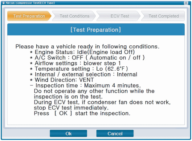
Prepare the vehicle as instructed on the KDS screen. (Turn the A/C off only)
[ECV2]
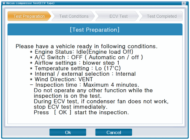
[ECV3]
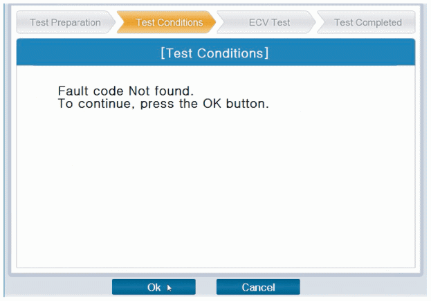
Before inspecting the ECV compressor, check for any other diagnostic trouble codes. If any are present, repair those first. If not, press the "OK" button to continue.
[ECV4]
Start the inspection.
[ECV5]
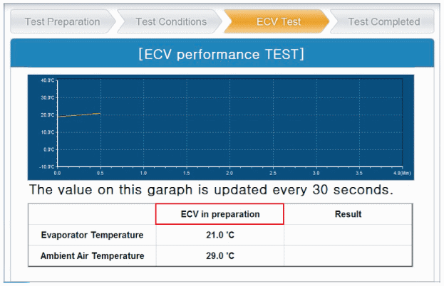
[ECV6]
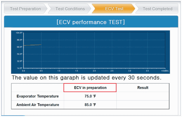
Check the inspection result.
[ECV7]
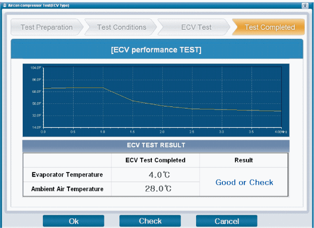
[ECV8]
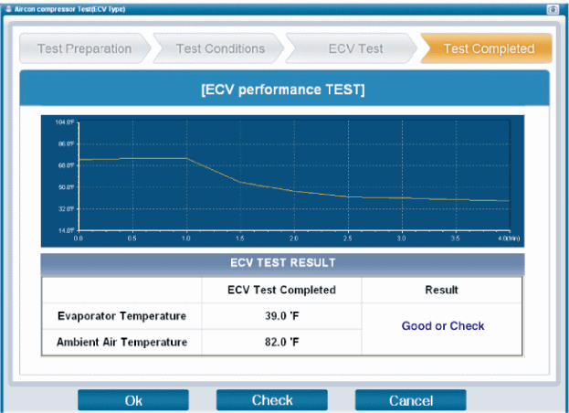
If the result is "Check", press "Check" and follow the instructions on the screen.
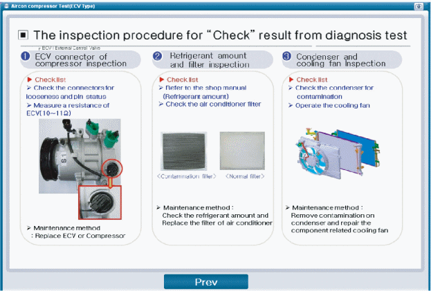
Inspect the ECV again, starting from the first step.
DISASSEMBLY
Remove the right front wheel.
(Refer to Suspension - "Wheel")
Loosen the drive belt.
D 1.6 U2 TCI (refer to Engine Mechanical – Drive Belt)
G 1.0 T-GDI KAPPA (refer to Engine Mechanical – Drive Belt)
G 1.2 MPI KAPPA (refer to Engine Mechanical – Drive Belt)
G 1.4 MPI KAPPA (refer to Engine Mechanical – Drive Belt)
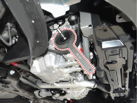
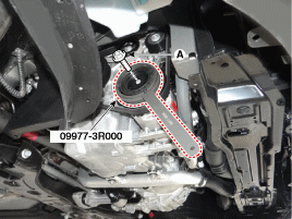
Remove the center bolt (A) and hub bolts (B) while holding the pulley/hub assembly with the screw removal tool (0977-3R000).
Tightening torque: 15~21 N·m
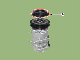
Remove the hub (A) and shim (split washer) (B). Be careful not to lose the shim.
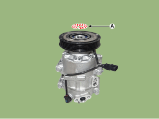
Remove the snap ring (A) from the pulley using pliers. Discard it.
Installation is performed in the reverse order of removal.
Test yourself
A quick Kia Stonic quiz: every answer comes with an explanation and a link to the manual page.