Backup Power Supply Circuit
DESCRIPTION
The backup power source circuit for the air conditioning amplifier assembly is shown in the diagram below. Power is supplied even when the ignition switch is OFF. This power supply is used to retain diagnostic trouble codes, etc.
WIRING DIAGRAM
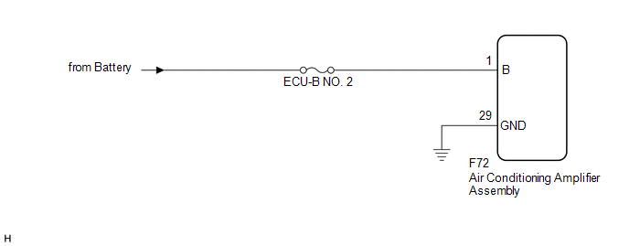
PRECAUTION / NOTICE / HINT
NOTICE:
Check the fuses for the circuits related to this system before performing the following procedure.
PROCEDURE
CHECK WIRE HARNESS AND CONNECTOR (AIR CONDITIONING AMPLIFIER ASSEMBLY - POWER SOURCE)
(a) Disconnect the connector from the air conditioning amplifier assembly. |
|
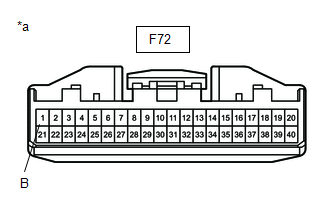
(b) Measure the voltage according to the value(s) in the table below.
Standard voltage:
Tester Connection | Condition | Specified Condition |
|---|---|---|
F72-1 (B) - Body ground |
Always |
11 à 14 V |
| NG |  |
REPAIR OR REPLACE HARNESS OR CONNECTOR |
|

CHECK WIRE HARNESS AND CONNECTOR (AIR CONDITIONING AMPLIFIER ASSEMBLY - BODY GROUND)
(a) Disconnect the F72 connector from the air conditioning amplifier assembly.
(b) Measure the resistance according to the value(s) in the table below.
Standard resistance:
Tester Connection | Condition | Specified Condition |
|---|---|---|
F72-29 (GND) - Body ground |
Always |
Below 1 Ω |
| OK | |
GO TO APPLICABLE SYSTEM AS INDICATED IN THE PROBLEM SYMPTOMS TABLE |
| NG | |
REPAIR OR REPLACE HARNESS OR CONNECTOR |