Pressure Sensor Circuit (B1423)
DESCRIPTION
This DTC is stored if the high pressure side refrigerant pressure is extremely low (or 176 kPa (1.8 kgf/cm2, 26 psi) or less)*1, (195 kPa (2.0 kgf/cm2, 28 psi) or less)*2, or extremely high (3,025 kPa (30.8 kgf/cm2, 439 psi) or more)*1, (2,812 kPa (28.7 kgf/cm2, 408 psi) or more)*2. The air conditioning pressure sensor, installed on the high pressure side pipe to detect the refrigerant pressure, sends a refrigerant pressure signal to the air conditioning amplifier assembly. The air conditioning amplifier assembly converts this signal into a pressure value based on the sensor characteristics and uses it to control the compressor.
- *1: for HFC-134a (R134a)
- *2: for HFO-1234yf (R1234yf)
DTC No. | Detection Item | DTC Detection Condition | Suspected Area | Memory |
|---|---|---|---|---|
B1423 |
Pressure Sensor Circuit |
One of the following conditions is met
|
|
- |
Vehicle Operating Conditions |
|||||
|---|---|---|---|---|---|
Sequence 1 | Sequence 2 | Sequence 3 | Sequence 4 |
||
Diagnostic Condition |
Ignition Switch in ON position |
○ |
○ |
○ |
○ |
Only when the outside air temperature is 5 °C or higher. |
○ |
○ |
○ |
○ |
|
Malfunction Status |
Open in Air Conditioning Pressure Sensor Circuit |
○ |
- |
- |
- |
Short in Air Conditioning Pressure Sensor Circuit |
- |
○ |
- |
- |
|
for HFC-134a (R134a): The high pressure side refrigerant pressure is extremely low (176 kPa (1.8 kgf/cm2, 26 psi) or less) |
- |
- |
○ |
- |
|
for HFO-1234yf (R1234yf): The high pressure side refrigerant pressure is extremely low (195 kPa (2.0 kgf/cm2, 28 psi) or less) |
- |
- |
○ |
- |
|
for HFC-134a (R134a): The high pressure side refrigerant pressure is extremely high (3,025 kPa (30.8 kgf/cm2, 439 psi) or more) |
- |
- |
○ |
○ |
|
for HFO-1234yf (R1234yf): The high pressure side refrigerant pressure is extremely high (2,812 kPa (28.7 kgf/cm2, 408 psi) or more) |
- |
- |
- |
○ |
|
Detection Duration |
4 seconds minimum |
4 seconds minimum |
4 seconds minimum |
4 seconds minimum |
|
Number of Trips |
1 trip(s) |
1 trip(s) |
1 trip(s) |
1 trip(s) |
|
HINT:
The DTC is output when the conditions for any one of the sequences in the table above are met.
WIRING DIAGRAM
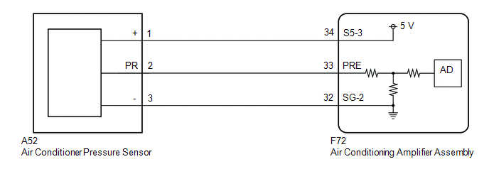
PROCEDURE
CHECK HARNESS AND CONNECTOR (POWER SOURCE CIRCUIT)
(a) Disconnect the air conditioning pressure sensor connector. |
|
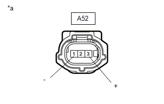
(b) Measure the voltage according to the value(s) in the table below.
Standard voltage:
Tester Connection | Ignition switch position | Specified Condition |
|---|---|---|
A52-1 (+) - A52-3 (-) |
Ignition Switch in ON position |
4,75 à 5,25 V |
| NG |  |
GO TO STEP 16 |
|

CHECK AIR CONDITIONING PRESSURE SENSOR (SENSOR SIGNAL CIRCUIT)
(a) Reconnect the A52 connector of the air conditioning pressure sensor.
(b) Remove the air conditioning amplifier assembly while keeping the connectors connected.
(c) Measure the voltage according to the value(s) shown in the table below.
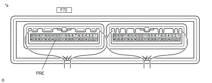
*a |
Component with Wire Harness Connected (A/C Amplifier Assembly) |
- |
- |
Standard voltage:
Tester Connection | Ignition switch position | Specified Condition |
|---|---|---|
F72-33 (PRE) - Body ground |
Ignition Switch in ON position (A/C switch: OFF) |
0,74 à 4,61 V |
HINT:
If the result is not as specified, there may be a malfunction in the air conditioning amplifier assembly, the air conditioning pressure sensor or the wire harness. The refrigerant quantity may also be incorrect.
| NG | |
GO TO STEP 10 |
|
CHECK AIR CONDITIONING PRESSURE SENSOR (SENSOR SIGNAL CIRCUIT)
(a) Measure the voltage under the following conditions.
Measurement condition:Item | Condition |
|---|---|
Vehicle Doors |
Fully open |
Temperature control setting |
MAX COLD |
Blower speed |
HI |
A/C switch |
ON |
Recirculation/Fresh Air Switch |
RECIRCULATION |
Indoor Temperature |
25 à 35 °C |
Engine speed |
2,000 rpm |
NOTICE:
- If the high pressure side refrigerant pressure becomes extremely high during the check (voltage exceeds 4.61 V), the fail-safe function stops compressor operation. Therefore, measure the voltage before the fail-safe function activates.
- The voltage must be measured for a certain period (approximately 10 minutes), as the malfunction may reoccur after some time.
HINT:
When the outside air temperature is low (below -1.5 °C), the compressor stops due to the operation of the cooler thermistor (ambient temperature sensor) and the No. 1 cooler thermistor (evaporator temperature sensor) to prevent the evaporator from freezing. In this case, perform the inspection in a warm place, inside the vehicle.
(1) Measure the voltage according to the value(s) shown in the table below.
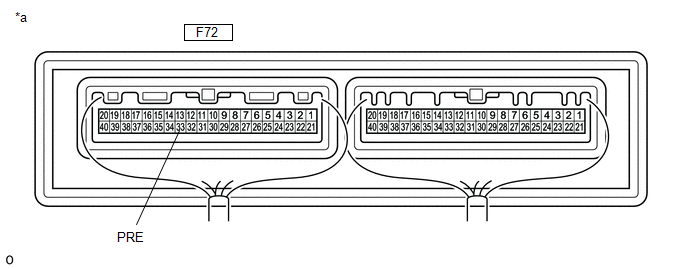
*a |
Component with Wire Harness Connected (A/C Amplifier Assembly) |
- |
- |
Standard voltage:
Tester Connection | Ignition switch position | Specified Condition |
|---|---|---|
F72-33 (PRE) - Body ground |
Ignition Switch in ON position (A/C switch: ON) |
0,74 à 4,61 V |
Result:
Result | Proceed to |
|---|---|
OK (when troubleshooting is performed using DTC) |
A |
OK (when troubleshooting is performed based on the Symptom Chart) |
B |
NG |
C |
| A | |
REPLACE AIR CONDITIONING AMPLIFIER ASSEMBLY |
| B | |
GO TO APPLICABLE SYSTEM AS INDICATED IN THE PROBLEM SYMPTOMS TABLE |
|
INSPECT COOLING FAN SYSTEM
(a) Check whether the cooling fan operates normally.
Click here
Result:
Result | Proceed to |
|---|---|
OK |
A |
NG |
B |
| B | |
PROCEED TO COOLING FAN SYSTEM |
|
CHARGE THE SYSTEM WITH REFRIGERANT
(a) Use the refrigerant recovery unit to recover the refrigerant.
(b) Evacuate the air conditioning system.
(c) Add an appropriate amount of refrigerant.
- for HFC-134a (R134a): Click here
- for HFO-1234yf (R1234yf): Click here
HINT:
If refrigerant is added and the system has not been evacuated properly (insufficient evacuation time), moisture remaining in the system will freeze in the cooler expansion valve, blocking the high pressure side flow. To correct this, the refrigerant must be recovered and the system properly evacuated. Add an appropriate amount of refrigerant and check whether the DTC is output.
|
CHECK WHETHER OTHER DTCS ARE OUTPUT
(a) Check again whether a DTC is output when the following conditions are met.
Measurement condition:Item | Condition |
|---|---|
Vehicle Doors |
Fully open |
Temperature control setting |
MAX COLD |
Blower speed |
HI |
A/C switch |
ON |
Recirculation/Fresh Air Switch |
RECIRCULATION |
Indoor Temperature |
25 à 35 °C |
Engine speed |
2,000 rpm |
NOTICE:
If the refrigerant pressure on the high-pressure side becomes high, the DTC will be stored. Operate the air conditioning system for a certain period (about 10 minutes), because the DTC may not be stored until the air conditioning has operated for some time.
HINT:
- When the outside air temperature is low (below -1.5 °C), the compressor stops due to the operation of the cooler thermistor (ambient temperature sensor) and the No. 1 cooler thermistor (evaporator temperature sensor) to prevent the evaporator from freezing. In this case, perform the inspection in a warm place, inside the vehicle.
- If refrigerant is added and the system has not been properly evacuated (insufficient vacuum time), moisture remaining in the system will freeze in the cooler expansion valve, blocking the flow on the high-pressure side. To correct this, recover the refrigerant, properly evacuate the system, then add the correct amount of refrigerant and check whether the DTC is output. If the DTC is not output after this procedure, the cooler drier in the cooler condenser assembly is unable to absorb moisture in the refrigerant cycle. Replace the cooler drier to complete the repair.
Result:
Result | Proceed to |
|---|---|
DTC B1423 is output |
A |
DTC B1423 is not output |
B |
| B | |
REPLACE COOLER CONDENSER ASSEMBLY |
|
REPLACE COOLER EXPANSION VALVE
(a) Install a new cooler expansion valve.
Click here
HINT:
Install a new cooler expansion valve if it is blocked or clogged.
|
CHARGE THE SYSTEM WITH REFRIGERANT
(a) Use the refrigerant recovery unit to recover the refrigerant.
(b) Evacuate the air conditioning system.
(c) Add an appropriate amount of refrigerant.
- for HFC-134a (R134a): Click here
- for HFO-1234yf (R1234yf): Click here
HINT:
If refrigerant is added and the system has not been evacuated properly (insufficient evacuation time), moisture remaining in the system will freeze in the cooler expansion valve, blocking the high pressure side flow. To correct this, the refrigerant must be recovered and the system properly evacuated. Add an appropriate amount of refrigerant and check whether the DTC is output.
|
CHECK WHETHER OTHER DTCS ARE OUTPUT
(a) Check again whether a DTC is output when the following conditions are met.
Measurement condition:Item | Condition |
|---|---|
Vehicle Doors |
Fully open |
Temperature control setting |
MAX COLD |
Blower speed |
HI |
A/C switch |
ON |
Recirculation/Fresh Air Switch |
RECIRCULATION |
Indoor Temperature |
25 à 35 °C |
Engine speed |
2,000 rpm |
NOTICE:
If the refrigerant pressure on the high-pressure side becomes high, the DTC will be stored. Operate the air conditioning system for a certain period (about 10 minutes), because the DTC may not be stored until the air conditioning has operated for some time.
HINT:
- When the outside air temperature is low (below -1.5 °C), the compressor stops due to the operation of the cooler thermistor (ambient temperature sensor) and the No. 1 cooler thermistor (evaporator temperature sensor) to prevent the evaporator from freezing. In this case, perform the inspection in a warm place, inside the vehicle.
- If the refrigerant pressure is still not normal after replacing the cooler expansion valve with a new or good one, the cooler condenser assembly or the pipes may be clogged with dirt, dust or other foreign matter. In this case, clean or replace the cooler condenser assembly or the pipes.
Result:
Result | Proceed to |
|---|---|
DTC B1423 is not output |
A |
DTC B1423 is output |
B |
| A | |
END |
| B | |
CLEAN OR REPLACE COOLER CONDENSER ASSEMBLY |
CHECK HARNESS AND CONNECTOR (AIR CONDITIONER AMPLIFIER ASSEMBLY - AIR CONDITIONING PRESSURE SENSOR)
(a) Disconnect the A52 air conditioning pressure sensor connector.
(b) Disconnect the F72 air conditioning amplifier assembly connector.
(c) Measure the resistance according to the value(s) in the table below.
Standard resistance:
Tester Connection | Condition | Specified Condition |
|---|---|---|
A52-2 (PR) - F72-33 (PRE) |
Always |
Below 1 Ω |
A52-2 (PR) or F72-33 (PRE) - Body ground |
Always |
10 kΩ minimum |
| NG | |
REPAIR OR REPLACE HARNESS OR CONNECTOR |
|
CHECK FOR AIR CONDITIONING SYSTEM LEAK
(a) Install a manifold gauge set.
(b) Recover the refrigerant from the air conditioning system using a refrigerant recovery unit.
(c) Evacuate the air conditioning system and check that the vacuum can be maintained.
OK:
The vacuum in the air conditioning system can be maintained.
HINT:
If the vacuum cannot be maintained in the air conditioning system, there may be a refrigerant leak. In this case, repair or replace the air conditioning system part responsible for the leak.
| NG | |
GO TO STEP 15 |
|
CHARGE THE SYSTEM WITH REFRIGERANT
(a) Use the refrigerant recovery unit to recover the refrigerant.
(b) Evacuate the air conditioning system.
(c) Add an appropriate amount of refrigerant.
- for HFC-134a (R134a): Click here
- for HFO-1234yf (R1234yf): Click here
HINT:
If refrigerant is added and the system has not been evacuated properly (insufficient evacuation time), moisture remaining in the system will freeze in the cooler expansion valve, blocking the high pressure side flow. To correct this, the refrigerant must be recovered and the system properly evacuated. Add an appropriate amount of refrigerant and check whether the DTC is output.
|
CHECK WHETHER OTHER DTCS ARE OUTPUT
(a) Check again whether a DTC is output when the following conditions are met.
Measurement condition:Item | Condition |
|---|---|
Vehicle Doors |
Fully open |
Temperature control setting |
MAX COLD |
Blower speed |
HI |
A/C switch |
ON |
Recirculation/Fresh Air Switch |
RECIRCULATION |
Indoor Temperature |
25 à 35 °C |
Engine speed |
2,000 rpm |
NOTICE:
If the refrigerant pressure on the high-pressure side becomes high, the DTC will be stored. Operate the air conditioning system for a certain period (about 10 minutes), because the DTC may not be stored until the air conditioning has operated for some time.
HINT:
When the outside air temperature is low (below -1.5 °C), the compressor stops due to the operation of the cooler thermistor (ambient temperature sensor) and the No. 1 cooler thermistor (evaporator temperature sensor) to prevent the evaporator from freezing. In this case, perform the inspection in a warm place, inside the vehicle.
Result:
Result | Proceed to |
|---|---|
DTC B1423 is output |
A |
DTC B1423 is not output |
B |
NOTICE:
If the DTC was stored due to too little or too much refrigerant, the problem may have been resolved after performing the previous step. The most likely cause of insufficient refrigerant is a leak. The most likely cause of excessive refrigerant is adding more refrigerant than the proper level. Identify the area responsible for the refrigerant leak and perform the necessary repairs.
| B | |
END |
|
CHECK AIR CONDITIONING PRESSURE SENSOR
(a) Install a manifold gauge set.
(b) Reconnect the A52 air conditioning pressure sensor connector.
(c) Remove the air conditioning amplifier assembly, leaving the connectors connected.
(d) Turn the ignition switch to the ON position.
(e) Measure the voltage according to the value(s) in the table below.
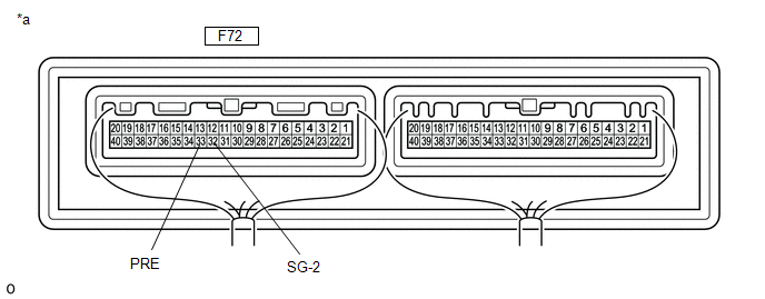
*a |
Component with Wire Harness Connected (A/C Amplifier Assembly) |
- |
- |
Standard voltage:
Tester Connection | Condition | Specified Condition |
|---|---|---|
F72-33 (PRE) - F72-32 (SG-2) |
Refrigerant pressure: Normal pressure (less than 3,025 kPa (30.8 kgf/cm2, 439 psi) and more than 176 kPa (1.8 kgf/cm2, 26 psi)) |
0,74 à 4,61 V |
| OK | |
REPLACE AIR CONDITIONING AMPLIFIER ASSEMBLY |
| NG | |
REPLACE AIR CONDITIONING PRESSURE SENSOR |
REPAIR A LEAK IN THE AIR CONDITIONING SYSTEM
(a) Identify the source of the refrigerant leak.
- for HFC-134a (R134a): Click here
- for HFO-1234yf (R1234yf): Click here
(b) Repair the identified area of the air conditioning system.
(c) Evacuate the air conditioning system.
Result:
Result | Proceed to |
|---|---|
for HFC-134a (R134a) |
A |
for HFO-1234yf (R1234yf) |
B |
| A | |
CHARGE THE SYSTEM WITH REFRIGERANT |
| B | |
CHARGE THE SYSTEM WITH REFRIGERANT |
CHECK HARNESS AND CONNECTOR (AIR CONDITIONER AMPLIFIER ASSEMBLY - AIR CONDITIONING PRESSURE SENSOR)
(a) Disconnect the F72 connector from the air conditioning amplifier assembly.
(b) Disconnect the A52 air conditioning pressure sensor connector.
(c) Measure the resistance according to the value(s) in the table below.
Standard resistance:
Tester Connection | Condition | Specified Condition |
|---|---|---|
A52-1 (+) - F72-34 (S5-3) |
Always |
Below 1 Ω |
A52-3 (-) - F72-32 (SG-2) |
Always |
Below 1 Ω |
A52-1 (+) or F72-34 (S5-3) - Body ground |
Always |
10 kΩ minimum |
A52-3 (-) or F72-32 (SG-2) - Body ground |
Always |
10 kΩ minimum |
| OK | |
REPLACE AIR CONDITIONING AMPLIFIER ASSEMBLY |
| NG | |
REPAIR OR REPLACE HARNESS OR CONNECTOR |