Compressor Solenoid Circuit (B1451)
DESCRIPTION
In this circuit, the Compressor with Pulley (Compressor Solenoid) receives a refrigerant compression request signal from the air conditioning amplifier assembly.
Based on this signal, the Compressor with Pulley (Compressor Solenoid) changes the compression level.
DTC No. | Detection Item | DTC Detection Condition | Suspected Area | Memory |
|---|---|---|---|---|
B1451 |
Compressor Solenoid Circuit |
One of the following conditions is met
|
|
- |
Vehicle Operating Conditions |
|||
|---|---|---|---|
Sequence 1 | Sequence 2 |
||
Diagnostic Condition |
Ignition Switch in ON position |
○ |
○ |
Malfunction Status |
Open in Compressor Solenoid Valve Circuit |
○ |
- |
Short in Compressor Solenoid Valve Circuit |
- |
○ |
|
Detection Duration |
30 seconds minimum |
30 seconds minimum |
|
Number of Trips |
1 trip(s) |
1 trip(s) |
|
HINT:
The DTC is output when the conditions for any one of the sequences in the table above are met.
WIRING DIAGRAM
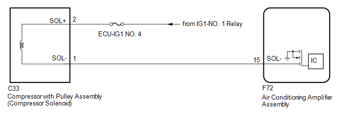
PRECAUTION / NOTICE / HINT
NOTICE:
Check the fuses for the circuits related to this system before performing the following procedure.
PROCEDURE
INSPECT COMPRESSOR WITH PULLEY ASSEMBLY (COMPRESSOR SOLENOID)
(a) Remove the Compressor with Pulley (Compressor Solenoid).
Click here
(b) Inspect the Compressor with Pulley (Compressor Solenoid).
Click here
| NG |  |
REPLACE COMPRESSOR WITH PULLEY ASSEMBLY (COMPRESSOR SOLENOID) |
|

CHECK WIRE HARNESS AND CONNECTOR (COMPRESSOR WITH PULLEY (COMPRESSOR SOLENOID) - POWER SOURCE)
(a) Measure the resistance according to the value(s) in the table below.
Standard voltage:
Tester Connection | Ignition switch position | Specified Condition |
|---|---|---|
C33-2 (SOL+) - Body Ground |
Ignition Switch in ON position |
11 à 14 V |
| NG | |
REPAIR OR REPLACE HARNESS OR CONNECTOR |
|
CHECK WIRE HARNESS AND CONNECTOR (COMPRESSOR WITH PULLEY (COMPRESSOR SOLENOID) - AIR CONDITIONING AMPLIFIER ASSEMBLY)
(a) Disconnect the F72 connector from the air conditioning amplifier assembly.
(b) Measure the resistance according to the value(s) in the table below.
Standard resistance:
Tester Connection | Condition | Specified Condition |
|---|---|---|
C33-1 (SOL-) - F72-15 (SOL-) |
Always |
Below 1 Ω |
C33-1 (SOL-) or F72-15 (SOL-) - Body Ground |
Always |
10 kΩ minimum |
Result:
Result | Proceed to |
|---|---|
NG |
A |
OK (when troubleshooting is performed using the Symptom Table) |
B |
OK (when troubleshooting is performed using DTC) |
C |
| A | |
REPAIR OR REPLACE HARNESS OR CONNECTOR |
| B | |
GO TO APPLICABLE SYSTEM AS INDICATED IN THE PROBLEM SYMPTOMS TABLE |
|
CHECK WHETHER DTCs ARE OUTPUT
(a) Clear the DTCs.
Click here
(b) Check DTCs.
Click here
Result:
Result | Proceed to |
|---|---|
No DTCs are output |
A |
DTCs are output |
B |
| A | |
USE SIMULATION METHOD TO CHECK |
| B | |
REPLACE AIR CONDITIONING AMPLIFIER ASSEMBLY |