Blower Motor Circuit
DESCRIPTION
The blower motor sub-assembly with fan is activated by signals from the air conditioning amplifier assembly via the blower resistor. The blower motor speed signals are transmitted according to changes in the duty cycle. The blower motor speed decreases as the duty cycle becomes larger, and increases as the duty cycle becomes smaller.
WIRING DIAGRAM
PRECAUTION / NOTICE / HINT
NOTICE:
Check the fuses for the circuits related to this system before performing the following procedure.
PROCEDURE
PERFORM ACTIVE TEST USING TECHSTREAM (BLOWER MOTOR)
(a) Connect the Techstream to the DLC3.
(b) Turn the ignition switch to ON.
(c) Turn on the Techstream.
(d) Select the following menu items: Body Electrical / Air Conditioner / Active Test.
(e) Perform the Active Test by following the Techstream instructions.
Body Electrical > Air Conditioner > Active TestTester display | Item | Control Range | Diagnostic Note |
|---|---|---|---|
Blower Motor |
Blower motor sub-assembly with fan |
Min.: 0 Max.: 100 |
Operates between 0 and 100% |
Blower Motor
Result:
Result | Proceed to |
|---|---|
OK |
A |
NG (the blower motor with fan sub-assembly does not operate) |
B |
NG (the blower motor with fan sub-assembly operates but does not change speed) |
C |
| A | GO TO APPLICABLE SYSTEM AS INDICATED IN THE PROBLEM SYMPTOMS TABLE |
| C | GO TO STEP 6 |
|

CHECK WIRE HARNESS AND CONNECTOR (AIR CONDITIONING WIRE HARNESS ASSEMBLY (BLOWER ASSEMBLY) - POWER SOURCE)
(a) Disconnect the air conditioning wire harness assembly (blower assembly) connector. |
|
(b) Measure the voltage according to the value(s) in the table below.
Standard voltage:
Tester Connection | Condition | Specified Condition |
|---|---|---|
A83-1 - A83-2 |
Always |
11 à 14 V |
(c) Measure the resistance according to the value(s) in the table below.
Standard resistance:
Tester Connection | Condition | Specified Condition |
|---|---|---|
A83-1 - Body ground |
Always |
Below 1 Ω |
| NG | REPAIR OR REPLACE HARNESS OR CONNECTOR |
|
INSPECT AIR CONDITIONING WIRE HARNESS ASSEMBLY (BLOWER ASSEMBLY)
(a) Remove the air conditioning wire harness assembly (blower assembly).
Click here
(b) Measure the resistance according to the value(s) in the table below. Standard resistance:
|
|
| NG | REPLACE AIR CONDITIONING WIRE HARNESS ASSEMBLY (BLOWER ASSEMBLY) |
|
CHECK AIR CONDITIONING WIRE HARNESS ASSEMBLY (HEATER UNIT SUBASSEMBLY)
(a) Remove the air conditioning wire harness assembly (heater unit subassembly).
Click here
(b) Measure the resistance according to the value(s) in the table below. Standard resistance:
|
|
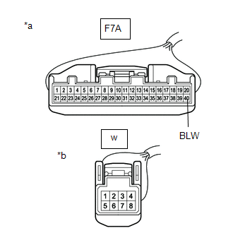
| NG | REPLACE AIR CONDITIONING WIRE HARNESS ASSEMBLY (HEATER UNIT SUB-ASSEMBLY) |
|
CHECK BLOWER RESISTOR
(a) Reconnect the F7b blower resistor connector.
(b) Reconnect the w air conditioning wire harness assembly (blower assembly) connector.
(c) Measure the voltage according to the value(s) shown in the table below. Standard voltage:
|
|
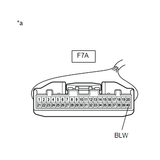
| NG | REPLACE BLOWER RESISTOR |
|
CHECK AIR CONDITIONING AMPLIFIER ASSY
(a) Reconnect connectors F7A and F72 of the air conditioning amplifier assembly.
(b) Turn the ignition switch to ON.
(c) Set the blower switch to Lo.
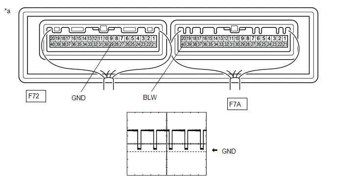
(d) Connect an oscilloscope to terminals F72-29 (GND) and F7A-40 (BLW) of the air conditioning amplifier assembly and check the waveform.
OK:
The waveform is the same as that shown in the diagram.
HINT:
The waveform varies depending on the blower speed.
Item | Content |
|---|---|
Oscilloscope Setting |
2 V/DIV., 1 ms/DIV. |
Vehicle Operating Conditions |
|
*a |
Component with Wire Harness Connected (Air Conditioning Amplifier Assembly) |
- |
- |
| NG | REPLACE AIR CONDITIONING AMPLIFIER ASSEMBLY |
|
REPLACE BLOWER RESISTOR
(a) Replace the blower resistor with a new one or one in good condition.
Click here
|
PERFORM ACTIVE TEST USING TECHSTREAM (BLOWER MOTOR)
(a) Connect the Techstream to the DLC3.
(b) Turn the ignition switch to ON.
(c) Turn on the Techstream.
(d) Select the following menu items: Body Electrical / Air Conditioner / Active Test.
(e) Perform the Active Test by following the Techstream instructions.
Body Electrical > Air Conditioner > Active TestTester display | Item | Control Range | Diagnostic Note |
|---|---|---|---|
Blower Motor |
Blower motor sub-assembly with fan |
Min.: 0 Max.: 100 |
Operates between 0 and 100% |
Blower Motor
| OK | END (BLOWER RESISTOR WAS FAULTY) |
| NG | REPLACE BLOWER ASSEMBLY (BLOWER MOTOR SUB-ASSEMBLY WITH FAN) |