Evaporator Temperature Sensor Circuit (B1413)
DESCRIPTION
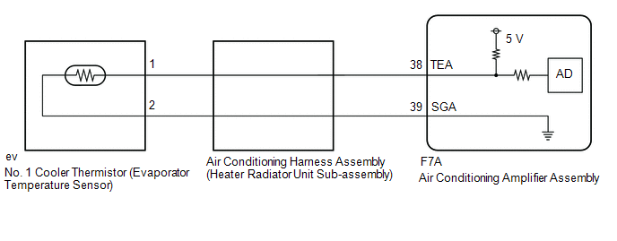
The Cooler Thermistor No. 1 (Evaporator Temperature Sensor) is installed on the evaporator of the air conditioning unit to detect the temperature of the cooled air passing through the evaporator, and is used to control the air conditioning system. It sends signals to the A/C amplifier assembly. The resistance of the Cooler Thermistor No. 1 (Evaporator Temperature Sensor) changes according to the temperature of the cooled air passing through the evaporator. The resistance increases as the temperature decreases. The resistance decreases as the temperature increases.
The A/C amplifier assembly applies a voltage (5 V) to the Cooler Thermistor No. 1 (Evaporator Temperature Sensor) and detects voltage changes as the resistance of the Cooler Thermistor No. 1 (Evaporator Temperature Sensor) changes. This sensor is used to prevent frost formation.
DTC No. | Detection Item | DTC Detection Condition | Suspected Area | Memory |
|---|---|---|---|---|
B1413 |
Evaporator Temperature Sensor Circuit |
One of the following conditions is met
|
|
Stored (4 seconds minimum)* |
- *: The A/C amplifier assembly stores this DTC if the malfunction occurs within the time period shown in parentheses.
Vehicle Operating Conditions |
|||
|---|---|---|---|
Sequence 1 | Sequence 2 |
||
Diagnostic Condition |
Ignition Switch in ON position |
○ |
○ |
Malfunction Status |
Open in No. 1 Cooler Thermistor (Evaporator Temperature Sensor) Circuit |
○ |
- |
Short in No. 1 Cooler Thermistor (Evaporator Temperature Sensor) Circuit |
- |
○ |
|
Detection Duration |
4 seconds minimum |
4 seconds minimum |
|
Number of Trips |
1 trip(s) |
1 trip(s) |
|
HINT:
The DTC is output when the conditions for any one of the sequences in the table above are met.
WIRING DIAGRAM
PROCEDURE
READ VALUE USING TECHSTREAM (EVAPORATOR FIN THERMISTOR)
(a) Connect the Techstream to the DLC3.
(b) Turn the ignition switch to ON.
(c) Turn on the Techstream.
(d) Select the following menu items: Body Electrical / Air Conditioner / Data List.
(e) Read the Data List by following the instructions on the Techstream.
Body Electrical > Air Conditioner > Data ListTester display | Item | Range | Normal Condition | Diagnostic Note |
|---|---|---|---|---|
Evaporator Fin Thermistor |
No. 1 Cooler Thermistor (Evaporator Temperature Sensor) |
Min.: -29,70 °C Max.: 60 °C |
Actual Evaporator Temperature Displayed |
- |
Evaporator Fin Thermistor
OK:
The displayed value is within the specifications in the normal condition column.
Result:
Result | Proceed to |
|---|---|
NG |
A |
OK (when troubleshooting is performed based on the Symptom Chart) |
B |
OK (when troubleshooting is performed using DTC) |
C |
| B |  |
GO TO APPLICABLE SYSTEM AS INDICATED IN THE PROBLEM SYMPTOMS TABLE |
| C | |
GO TO STEP 4 |
|

INSPECT COOLER THERMISTOR NO. 1 (EVAPORATOR TEMPERATURE SENSOR)
(a) Remove the Cooler Thermistor No. 1 (Evaporator Temperature Sensor).
Click here
(b) Inspect the Cooler Thermistor No. 1 (Evaporator Temperature Sensor).
Click here
| NG | |
REPLACE COOLER THERMISTOR NO. 1 (EVAPORATOR TEMPERATURE SENSOR) |
|
CHECK AIR CONDITIONING WIRE HARNESS ASSEMBLY (HEATER UNIT SUBASSEMBLY)
(a) Remove the air conditioning wire harness assembly (heater unit sub-assembly).
Click here
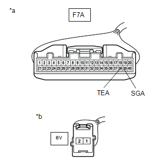
(b) Measure the resistance according to the value(s) in the table below. Standard resistance:
|
|
| OK | |
REPLACE AIR CONDITIONING AMPLIFIER ASSEMBLY |
| NG | |
REPLACE AIR CONDITIONING WIRE HARNESS ASSEMBLY (HEATER UNIT SUB-ASSEMBLY) |
CHECK WHETHER DTCs ARE OUTPUT
(a) Clear the DTCs.
Click here
(b) Check DTCs.
Click here
Result:
Result | Proceed to |
|---|---|
No DTCs are output |
A |
DTCs are output |
B |
| A | |
USE SIMULATION METHOD TO CHECK |
| B | |
REPLACE AIR CONDITIONING AMPLIFIER ASSEMBLY |