Stop Light Relay Circuit (C1A4B)
DESCRIPTION
The skid control ECU (brake actuator assembly) sends a stop light operation request signal to the stop light switch assembly. If the skid control ECU (brake actuator assembly) detects a malfunction in the stop light switch assembly circuit, the millimeter wave radar sensor assembly stores DTC C1A4B.
DTC No. | Detection Item | DTC Detection Condition | Suspected Area |
|---|---|---|---|
C1A4B |
Stop light relay circuit |
Monitor Description:
Malfunction Threshold: One of the following conditions is met:
|
|
Vehicle Operating Conditions |
|||
|---|---|---|---|
Sequence 1 | Sequence 2 |
||
Diagnostic Condition |
Ignition switch in ON position and battery voltage between 11 and 14 V. |
○ |
○ |
Malfunction Status |
When the stop light output (STPO) signal is on, no signal is sent to terminal STP2. |
○ |
- |
When the stop light output (STPO) signal is off, the signals sent to terminal STP and terminal STP2 of the skid control ECU (brake actuator assembly) are different. |
- |
○ |
|
Detection Duration |
0.3 seconds |
0.3 seconds |
|
Number of Trips |
1 trip(s) |
1 trip(s) |
|
HINT:
The DTC is output when the conditions for any one of the sequences in the table above are met.
WIRING DIAGRAM
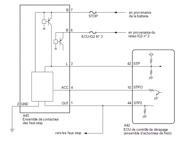
PRECAUTION / NOTICE / HINT
NOTICE:
- The Pre-Collision System uses the CAN communication system. First, make sure there are no malfunctions in the CAN communication system. Refer to How to Use Troubleshooting.
Click here

- Check the fuses for the circuits related to this system before performing the following inspection procedure.
PROCEDURE
CHECK DTCs (VEHICLE STABILITY CONTROL SYSTEM)
HINT:
The Pre-Collision Safety System DTC C1A4B may be stored due to a malfunction in the VSC system. Therefore, check and perform troubleshooting of the VSC system DTCs first.
(a) Check the DTCs.
Click here
Result:
Result | Proceed to |
|---|---|
VSC-related DTCs are not output |
A |
VSC-related DTCs are output |
B |
| B |  |
GO TO VEHICLE STABILITY CONTROL SYSTEM |
|

READ DTCs (PRE-COLLISION SYSTEM)
(a) Clear the DTCs.
Click here
(b) Make sure the DTC detection conditions are met.
HINT:
If the detection conditions are not met, the system is unable to detect malfunctions.
(c) Check the DTCs.
Click here
Result:
Result | Proceed to |
|---|---|
DTC C1A4B is output |
A |
DTC C1A4B is not output |
B |
| B | |
USE SIMULATION METHOD TO CHECK |
|
REPLACE MILLIMETER WAVE RADAR SENSOR ASSEMBLY
(a) Replace the millimeter wave radar sensor assembly.
Click here
(b) Adjust the millimeter wave radar sensor assembly.
Click here
|
READ DTCs (PRE-COLLISION SYSTEM)
HINT:
After performing the radar sensor axis adjustment, if the same DTC is still output after the DTC detection conditions are met, replace the millimeter wave radar sensor assembly.
(a) Clear the DTCs.
Click here
(b) Make sure the DTC detection conditions are met.
HINT:
If the detection conditions are not met, the system is unable to detect malfunctions.
(c) Check the DTCs.
Click here
Result:
Result | Proceed to |
|---|---|
DTC C1A4B is not output |
A |
DTC C1A4B is output |
B |
| A | |
END (MILLIMETER WAVE RADAR SENSOR ASSY WAS MALFUNCTIONING) |
| B | |
REPLACE SKID CONTROL ECU (BRAKE ACTUATOR ASSEMBLY) |