How to Use Troubleshooting
PRECAUTION / NOTICE / HINT
HINT:
- Use these procedures to troubleshoot the Pre-Collision System.
- *: Use the Techstream.
PROCEDURE
VEHICLE BROUGHT TO WORKSHOP
|

CUSTOMER PROBLEM ANALYSIS AND SYMPTOM CONFIRMATION
Customer Problem Analysis for the Pre-Collision System | Vehicle Brought to Workshop |
||||||
|---|---|---|---|---|---|---|---|
Year | Month | Day |
|||||
Dealer Name |
Person in Charge at Head Office |
Telephone Number |
|||||
Workshop Nameplate |
Person in Charge at Workshop |
||||||
Chassis Type |
Frame No. |
First Registration Year |
Total Distance Driven |
||||
Customer Problems (include details) |
does not operate |
||||||
Does not operate normally |
|||||||
Date the malfunction first occurred (since when) |
Year |
Month |
Day |
Approximate time |
|||
Date of last check |
Year |
Month |
Day |
||||
Frequency of problem symptoms |
Once / Occasionally (per day, per month) / Every time certain conditions are met ( ) |
||||||
Time |
Sunny / Cloudy / Rain / Snow (snowfall level: cm) / Other ( ) |
Vehicle speed |
Approx. ( ) km/h |
||||
Location |
Prefecture (if possible, attach a map) |
||||||
Route (where the vehicle turned, where the driver tried to drive, etc.) * Describe the conditions present immediately when the problem occurred, in as much detail as possible. |
Symptom Occurrence Conditions  |
||||||
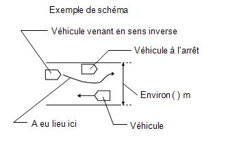 |
|||||||
Surrounding Road Conditions Describe whether there are signs, metallic objects on the road (manhole covers), guardrails, pipes, safety cones, barriers, etc. |
|||||||
Urban area / Suburbs / Highway / Other ( ) |
Road Surface Conditions |
Temperature |
Approx. °C ( °F) |
||||
Driving Direction |
Straight ahead / Right turn / Left turn / Right curve / Left curve |
Snow drift(s) |
Y / N |
||||
Traffic lane |
Number of lanes on one side (lanes) / ( ) lane(s) counting from the left |
Backlight |
Y / N |
||||
Condition of the detection sensor around the exterior area |
No foreign matter / Foreign matter (water, snow, ice, other) |
||||||
Additional information regarding the exterior condition of the vehicle (other than that mentioned above) |
|||||||
DTC |
First time (when the vehicle was brought to the workshop) |
||||||
Second time (after clearing the DTCs) |
|||||||
Switch operating condition |
Pre-collision system cancel switch |
Far / Mid / Near / OFF |
VSC OFF Switch |
ON / OFF |
|||
Serial number of the main part * Fill in when removing, installing or replacing the part |
Front Area Recognition Camera |
||||||
Describe the items on the right in as much detail as possible. |
Driver operation |
Accelerator pedal depressed / Brake pedal depressed / Steering wheel operated |
Time elapsed after engine start |
Approximately ( ) minutes |
|||
Tire pressure check result |
Front: Left ( ) kPa Right ( ) kPa Specified ( ) kPa |
||||||
Rear: Left ( ) kPa Right ( ) kPa Specified ( ) kPa |
|||||||
Sensor optical axis check result |
Front Area Recognition Camera |
Accident history |
Y / N |
||||
Millimeter wave radar sensor assembly |
Accident history |
Y / N |
|||||
Vehicle modifications |
Y ( ) / N |
||||||
Items attached or mounted around the windshield glass |
Drive recorder* / Radar detector / Navigation unit (genuine / non-genuine) / ETC / Charms or toys / Other: *: If information about the item is important for the investigation, make sure to obtain the item if the customer gives permission. |
||||||
|
CHECK BATTERY VOLTAGE
(a) Measure the battery voltage.
Standard voltage:
11 à 14 V
If the voltage is below 11 V, charge or replace the battery before proceeding to the next step.
|
INSPECT MILLIMETER WAVE RADAR SENSOR ASSEMBLY (BEAM AXIS MISALIGNMENT READING)*
(a) Adjust the reflector height.
Click here
(b) Position the reflector.
Click here
(c) Connect the Techstream to the DLC3.
(d) Turn the ignition switch to the ON position.
(e) Turn on the Techstream.
(f) Set the cruise control main switch to ON.
(g) Select the following menu items: Body Electrical / Pre-Collision 2 / Utility / Front Beam Axis Misalignment Reading.
(h) Check the misalignment value and make a note of it.
Body Electrical > Pre-Collision 2 > UtilityFront Beam Axis Misalignment Reading
(i) Select the following menu items: Body Electrical / Pre-Collision 2 / Utility / Front Beam Axis Offset Reading.
(j) Check the offset value and make a note of it.
Body Electrical > Pre-Collision 2 > UtilityFront Beam Axis Offset Reading
|
CHECK CAN COMMUNICATION SYSTEM*
(a) Using the Techstream, check whether the CAN communication system operates normally.
HINT:
Refer to the CAN Bus Check section in the CAN communication system.
Click here
OK:
The CAN communication system operates normally.
| NG |  |
GO TO CAN COMMUNICATION SYSTEM |
|
CHECK WARNING LIGHT
(a) Check the condition of the warning lights on the instrument cluster assembly.
Result:
Result | Proceed to |
|---|---|
Only the PCS light flashes |
A |
The PCS light does not flash |
|
The PCS light and other lights come on or flash |
B |
| B | |
GO TO MALFUNCTIONING SYSTEM |
|
CHECK MULTI-DISPLAY
(a) Make sure the pre-collision system warning message is displayed on the multi-display in the instrument cluster assembly.
Result:
Result | Proceed to |
|---|---|
The message "Pre-Collision System Malfunction Visit Your Dealer" is displayed |
A |
One of the following messages is displayed
|
B |
The warning message is not displayed |
C |
| B | |
REFER TO SYMPTOM TROUBLESHOOTING TABLE |
| C | |
CHECK CONDITIONS WHEN PRE-COLLISION SYSTEM DID NOT OPERATE |
|
READ DTCs (PRE-COLLISION SYSTEM)
HINT:
Refer to Check / Clear DTCs.
Click here
(a) Check whether DTCs are output and record them.
Body Electrical > Pre-Collision 2 > Trouble Codes(b) Clear the DTCs.
Body Electrical > Pre-Collision 2 > Clear DTCs(c) Check the DTCs again.
(1) Try to simulate the conditions in which the malfunction occurred and check whether the DTCs are output again.
Body Electrical > Pre-Collision 2 > Trouble CodesResult:
Result | Proceed to |
|---|---|
The malfunction recurs but no DTCs are output |
A |
The malfunction cannot be reproduced and no DTCs are output |
B |
DTCs are output |
C |
| B | |
GO TO SYMPTOM SIMULATION |
| C | |
GO TO DTC CHART |
|
SYMPTOM TROUBLESHOOTING TABLE
HINT:
Refer to the symptom troubleshooting table.
Click here
Result:
Result | Proceed to |
|---|---|
The malfunction is not listed in the Problem Symptoms Table |
A |
The malfunction is listed in the Problem Symptoms Table |
B |
| B | |
GO TO STEP 12 |
|
GENERAL ANALYSIS AND TROUBLESHOOTING*
(a) ECU terminals
Click here
(b) Data List/Active Test
Click here
|
ADJUST, REPAIR OR REPLACE
NOTICE:
When the millimeter wave radar sensor assembly is replaced with a new one, the radar sensor beam axis must be adjusted.
Click here
|
CONFIRMATION TEST
| NEXT | |
END |