Cylinder Head
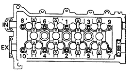
Cylinder head bolt tightening sequence (engines 1.3 L)
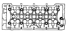
Cylinder head bolt tightening sequence (engines 1.6 L and 1.8 L)
* Perform the work on a cold engine.
Removal
PROCEDURE
1. Disconnect the battery ground cable.
* If the car stereo is equipped with an anti-theft system, make sure you know the activation code before disconnecting the battery ground cable.
2. Drain the coolant and remove the spark plugs (see subsection 2.8.2).
3. Drain the engine oil and remove the oil filter (see subsection 2.5.2).
4. Remove the throttle body, injectors and fuel rail (see subsection 5.12).
5. Remove the intake manifold (see subsection 3.1.1.4).
6. Remove the exhaust manifold (see subsection 3.1.1.5).
* The intake manifold and exhaust manifold can be removed together with the cylinder head for final disassembly on a bench.
7. Remove the driven camshaft sprocket (see subsection 3.1.1.8) and the timing belt (see subsection 3.1.1.6).
8. Remove the camshafts and tappets (see subsection 3.1.1.9, subsection 3.1.1.10).
9. Remove the alternator and the ignition distributor (see subsection 3.3.6 and subsection 3.3.11).
10. Mark and remove the remaining parts (cooling system pipe brackets, cables, hoses and wiring).
11. Mark and remove the remaining parts (cooling system pipe brackets, cables, hoses and wiring).
12. Disconnect the cooling system hoses from the cylinder head. After this operation, you can proceed to the final stage of cylinder head removal.
13. Using a hex key and extension, loosen the cylinder head bolts, loosening each bolt by 1/4 turn at a time. Loosen the bolts in the reverse order of the tightening sequence (see Figure Cylinder Head Bolt Tightening Sequence (Engines 1.3 L) and Figure Cylinder Head Bolt Tightening Sequence (Engines 1.6 L and 1.8 L)) to avoid distortion and cracks in the cylinder head.
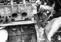
14. Remove the cylinder head. If the head does not come off easily, carefully pry the head from the transmission side at the boss. Do not separate the head at any other location.
15. Remove the remaining parts from the head that are required for inspection and thorough cleaning. Cylinder head repair operations are described in subsection 3.1.2.7).
Installation
PROCEDURE
1. Before installation, thoroughly clean the mating surfaces of the cylinder head and cylinder block.
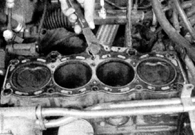
2. Scrape off carbon deposits and gasket material residue. The mating surfaces of the cylinder head and cylinder block must be completely clean to ensure a reliable seal.
3. Wash the cylinder head mating surface with lacquer thinner or acetone. If oil traces remain on the block surface, the head gasket will not seal the joint between head and block, and oil leaks will develop during operation. When working on the cylinder block, stuff clean rags into the cylinders to prevent solid particles from entering during cleaning. Remove dirt that has entered the cylinders with a vacuum cleaner or other suitable device.
4. Check the mating surfaces of the cylinder head and block for scoring, chips, pits and other damage. Minor damage can be removed with a file. If there is serious damage, the head or block must be resurfaced.
5. Cover the threaded holes in the cylinder head with adhesive tape and blow out all passages and holes with compressed air. Make sure the holes are clean. Wear safety goggles when working with compressed air.
6. Run a die over the thread of each bolt, with the bolt clamped in a vise, to remove corrosion and restore damaged threads. Dirt, rust, sealant residue and damaged threads make bolt installation difficult and can cause incorrect torque readings.
7. Install all parts removed during cylinder head disassembly.

8. Place a new gasket on the cylinder block, aligning it with the dowel pins. Note the "UP" mark on the gasket.
9. Carefully place the cylinder head on the block without disturbing the gasket position.
10. Before installing the bolts, lubricate the bolt head bearing surfaces with engine oil.
11. Hand-tighten the cylinder head bolts into their original positions. Short bolts go on the intake valve side, and long bolts on the exhaust valve side. Tighten the bolts to the specified torque in the sequence shown (see Figure Cylinder Head Bolt Tightening Sequence (Engines 1.3 L) and Figure Cylinder Head Bolt Tightening Sequence (Engines 1.6 L and 1.8 L)). On 1.3 L engines, tighten the cylinder head bolts in two stages, and on 1.6 and 1.8 L engines in three stages. Torque values are specified in subsection 3.1.1.1). In stages 2 and 3, turn the bolts an additional 1/4 turn (90°). If your torque wrench has no angle scale, mark the head of each bolt with paint and turn the bolt so the mark moves 90° from its original position (stage 2). On 1.6 L and 1.8 L engines, turn the bolts an additional 90°, i.e., each bolt must turn 180° relative to the position after stage 1.
12. Perform the remaining assembly operations in reverse order.
* If the intake camshaft cup plug on the cylinder head was removed during disassembly, coat the plug with RTV-type sealant before installing it in place.
13. Before installing the cylinder head cover, check and, if necessary, adjust the valve train clearances (see subsection 2.1).
14. After completing the work, fill the cooling system with coolant and restore the engine oil level (see subsection 2.3).
15. Start the engine and check for leaks. Set the ignition timing (see subsection 3.3.7) and test drive the vehicle.
Test yourself
A quick Toyota Corolla quiz: every answer comes with an explanation and a link to the manual page.