Camshafts and Tappets (1.3 L Engines)
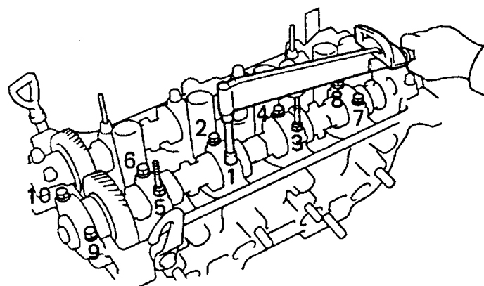
Tightening Sequence for Exhaust Camshaft Bearing Cap Bolts (Engines 1.3 L)
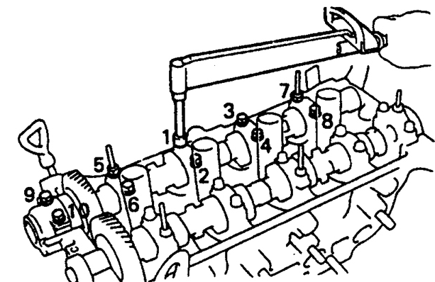
Tightening Sequence for Intake Camshaft Bearing Cap Bolts (Engines 1.3 L)
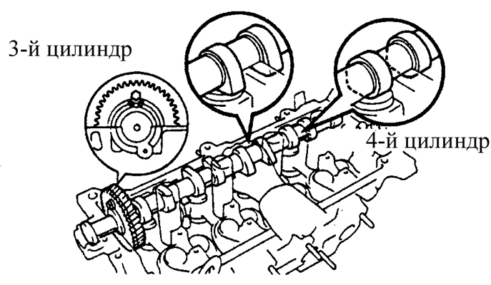
Timing Marks on Intake and Exhaust Camshaft Sprockets
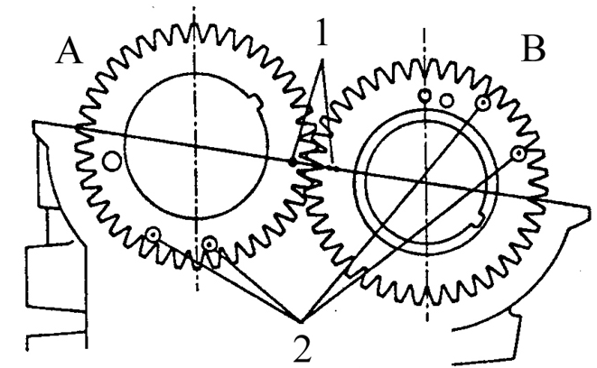
Two sets of timing marks on engines 1.3 L Do not use timing marks intended for other purposes when aligning the camshafts.
A. Exhaust camshaft
B. Intake camshaft
1. Timing marks
2. TDC timing marks
* Before starting the work, prepare two 6x1 mm bolts, 15–20 mm long, to be used as auxiliary bolts during disassembly.
Removal
PROCEDURE
1. Remove the cylinder head cover (see subsection 3.1.1.3).
2. Set the No. 1 piston to TDC on the compression stroke (see subsection 3.1.1.2).
3. Remove the ignition distributor (see subsection 3.3.6). Remove the driven camshaft sprocket (see subsection 3.1.1.8) and the timing belt (see subsection 3.1.1.6).
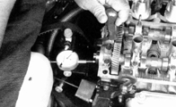
4. Measure the axial play of each camshaft using a dial indicator. Set the indicator to zero. Rock the camshaft firmly in the longitudinal direction (toward and away from you) and determine the axial play. If the play exceeds the specified limit, replace the camshaft and/or the cylinder head.
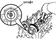
5. Turn the camshaft so that the auxiliary bolt access hole faces vertically upward. In this camshaft position, the cams of the first and third cylinders should press against the tappets with equal force under the action of the springs.
* The camshaft must be positioned exactly in this way to avoid damaging the cylinder head or the camshaft when removing it.
6. Remove the four bolts and the front bearing caps of the exhaust and intake camshafts. Remove the intake camshaft plug, and remove the exhaust camshaft seal.

7. Attach the auxiliary sprocket to the main camshaft sprocket with the prepared M6 bolt, 15–20 mm long, screwed into the threaded hole in the camshaft sprocket.
8. In the reverse of the indicated sequence (see figure Tightening Sequence for Exhaust Camshaft Bearing Cap Bolts (Engines 1.3 L)), loosen the remaining exhaust camshaft bearing cap bolts in several passes. Loosen each bolt by 1/4 turn per pass, until the bolts can be turned by hand. Remove the caps by lifting them straight up.
* As the center cap bolts are loosened, make sure the camshaft begins to move vertically in the bearings evenly. If any camshaft journal stops moving freely, or the camshaft is released with a tilt (which can be detected by the cams), repeat the procedure of loosening the bearing cap bolts, first retightening them to the specified torque in the indicated sequence. Do not force the camshaft out.
9. Remove the exhaust camshaft by lifting it upward.
10. In the reverse order of the sequence shown (see Fig. Intake camshaft bearing cap bolt tightening sequence (engines 1.3 L)), loosen the bolts of the remaining intake camshaft bearing caps in several steps. Loosen each bolt by 1/4 turn per step until the bolts can be turned by hand. Remove the caps by lifting them straight up.
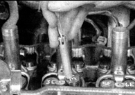
11. Wipe the oil off the tappet shims, mark them with a marker, and remove the tappets and shims.
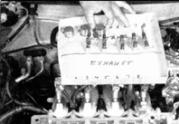
12. Store the bearing caps, tappets and shims in the order in which they were installed.
13. Clamp the intake camshaft by its hex journal in a vise with soft jaws.
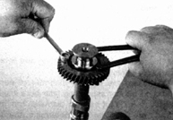
14. Using a tool with two locating pins, turn the auxiliary sprocket clockwise, then remove the auxiliary sprocket bolt that secures the main and auxiliary sprockets, and carefully release the tension, allowing the auxiliary sprocket to rotate counterclockwise until the spring is fully relaxed.

15. Remove the auxiliary sprocket snap ring using special snap ring pliers.
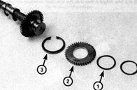
16. Remove the spring washer (1), the auxiliary sprocket (2) and the auxiliary sprocket spring (3).
Inspection
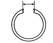
1. Measure the distance between the ends of the auxiliary sprocket spring in the free state and compare it with the specification. If the distance differs from the specification, replace the spring.
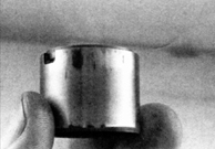
2. Check the condition of the tappet shims and tappets. Chips and deep wear are not permitted.
3. Measure the diameter of each tappet, then measure the diameter of the mating bore in the cylinder head. Determine the tappet clearance as the difference between the bore diameter in the cylinder head and the tappet diameter. If the clearance exceeds the specification, replace the tappet(s) or the cylinder head.
4. Check the bearing journals and cam lobes of the camshaft for signs of wear – grooves, pits, metal pickup – and signs of overheating (bluish areas or flaking). Check each cam lobe for delamination of the hardened layer.
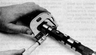
5. Measure each camshaft lobe with a micrometer and compare the dimensions with the specifications. If the dimension of at least one lobe is less than the specification, replace the camshaft.

6. Measure the diameter of the camshaft bearing journals with a micrometer and compare the dimensions with the specifications. If the diameter of at least one journal is less than the specification, replace the camshaft.
7. Check the bearing journal clearances for each camshaft.
8. Clean the camshaft bearing journals and bearing caps in lacquer thinner or acetone.
9. Carefully place the camshaft(s) into the cylinder head without the tappets, shims and intake camshaft auxiliary sprocket. Oil on the journals is not permitted.
10. Lay strips of Plastigauge plastic gauging wire across each camshaft bearing journal.
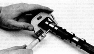
11. Install the camshaft bearing caps so that the arrows face the timing belt.
12. Tighten the bolts to the specified torque, turning each bolt by 1/4 turn per step.
* Turning the camshaft with the plastic gauge inserted is not permitted.
13. Loosen and remove the bolts and the caps.
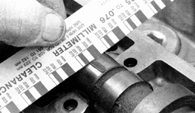
14. Compare the width of the crushed wire (at its widest point) with the scale on the package.
15. If the clearance in at least one journal exceeds the specification, replace the camshaft and/or the cylinder head.
16. Scrape off the remaining plastic with a fingernail or plastic tool, taking care not to scratch the journal or the inner surface of the cap.
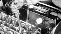
17. With the bearing caps temporarily installed, check the backlash of the camshaft sprocket meshing. Holding one camshaft by its hex journal with a wrench, check the amount of movement of the other camshaft sprocket. Compare the result with the specification. If the backlash exceeds the specification, replace both camshafts.
Installation
PROCEDURE
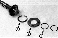

1. Assemble the intake camshaft with the springs and auxiliary sprocket. Install the spring washer (1), the auxiliary sprocket (2) and the auxiliary sprocket spring (3) (photo left), and secure all parts with the snap ring (photo right).
2. Install the auxiliary bolt, referring to step 7 of this subsection.
3. Install the tappets in their original positions, after lubricating the tappets and cylinder head bores with molybdenum disulfide grease. Make sure the tappet shims are in place.
4. Lubricate the bearing journals and cam lobes of the intake camshaft with molybdenum disulfide grease or assembly lube.
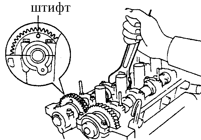
5. Position the intake camshaft so that the technological hole for the bolt is at the uppermost position, then install the camshaft on the cylinder head.
6. Install the intake camshaft bearing caps (except the front one) in their original positions, observing the numbering and the arrow orientation, which must face the timing belt.
7. Evenly, in several steps and following the sequence (see Fig. Intake camshaft bearing cap bolt tightening sequence (engines 1.3 L)), tighten the bolts until the caps are in full contact with the cylinder head. Do not tighten the bolts to final torque yet.
8. Install the exhaust tappets in their original positions, after lubricating the tappets with molybdenum disulfide grease. Make sure the tappet shims are in place.
9. Lubricate the bearing journals and cam lobes of the exhaust camshaft with molybdenum disulfide grease or assembly lube.
10. Align the timing marks on the intake and exhaust camshaft sprockets (see Fig. Timing marks on the intake and exhaust camshaft sprockets).
* Some engines have two sets of timing marks. Make sure the correct marks are aligned (see fig. Two Sets of Timing Marks on 1.3 L Engines).
11. Rotate the exhaust camshaft gear relative to the intake camshaft gear and evenly seat the exhaust camshaft in the cylinder head journal grooves, slightly turning the intake camshaft gear by the same angle in both directions.
12. Install the exhaust camshaft journal caps (except the front cap) in their original positions, observing the numbering and making sure the arrows point toward the timing belt.
13. Tighten the bolts until the caps make full contact with the cylinder head. Tighten the bolts evenly in several steps, following the tightening sequence. Do not fully tighten the bolts yet.
14. Remove the auxiliary bolt securing the main and auxiliary intake camshaft gears.
15. Apply RTV sealant to the contact surface between the intake camshaft front cover and the cylinder head.
* The cover must be installed immediately after applying sealant, before it hardens.
16. Install the front cover. Evenly, in several steps and following the sequence, tighten the two mounting bolts until the cover makes full contact with the cylinder head. Do not fully tighten the bolts yet.
17. Install the plug in the front end of the intake camshaft.
18. Tighten the intake camshaft journal cap bolts in several steps to the specified torque, in the specified sequence (see fig. Intake Camshaft Journal Cap Bolt Tightening Sequence (1.3 L Engines)).
19. Lubricate the sealing lip of a new seal with engine oil or multi-purpose grease and press the new seal into the cylinder head. After installation, the seal surface must be flush with the cylinder head surface.
20. Apply RTV sealant to the contact surface between the exhaust camshaft front cover and the cylinder head. Install the front cover. Evenly, in several steps and following the sequence, tighten the two mounting bolts until the cover makes full contact with the cylinder head. Do not fully tighten the bolts yet.
* The cover must be installed immediately after applying sealant, before it hardens.
21. Tighten the exhaust camshaft journal cap bolts in several steps to the specified torque (see subsection 3.1.1.1), in the specified sequence (see fig. Exhaust Camshaft Journal Cap Bolt Tightening Sequence (1.3 L Engines)).
22. Rotate the camshafts one or two full turns and check alignment of the timing marks. The marks must align.
23. Install the driven gear on the exhaust camshaft and tighten the gear bolt to the torque specified in subsection 3.1.1.1. Hold the camshaft with a wrench on the hex journal while tightening the bolt.
24. Install the timing belt (see subsection 3.1.1.6).
25. Perform the remaining installation steps in reverse order.
Test yourself
A quick Toyota Corolla quiz: every answer comes with an explanation and a link to the manual page.