Main and Connecting Rod Bearings
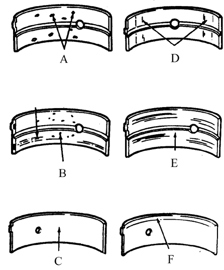
Types of Main and Connecting Rod Bearing Wear
A. Fatigue wear (arrows indicate craters or pits)
B. Scratches caused by dirt contamination (arrows indicate embedded dirt in the overlay material)
C. Excessive wear (arrow indicates wear-through of the bearing overlay over the entire surface)
D. Incorrect bearing installation (arrows indicate shiny, polished areas)
E. Insufficient lubrication (arrows indicate wear-through of the bearing overlay)
F. Journal taper (arrow indicates the ridge formed at the bearing edge)
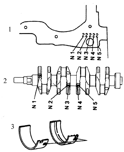
Location of Bearing and Journal Size Group Markings on 1.6 and 1.8 L Engines 1. On cylinder block: marks 1, 2 or 3
2. On crankshaft: marks 0, 1 or 2
3. On bearings: size group markings (from 1 to 5)
Inspection
Although the main and connecting rod bearings must be replaced during an engine overhaul, used bearings should be kept in their installed positions for careful inspection, since signs of wear on these parts allow you to assess the overall condition of the engine.
Crankshaft bearing failure is caused by insufficient lubrication, the presence of dirt and foreign particles, engine overloading, and corrosion. Regardless of the cause of bearing failure, it must be eliminated before final engine assembly to prevent repeated damage to these parts.
When inspecting the bearings, remove them from their seats (from the cylinder block, crankshaft main bearing caps, connecting rod caps and connecting rods) and lay them out on a clean surface in the same order in which they were installed in the engine. This will identify the specific crankshaft journal where the bearing experienced excessive wear.
Dirt and foreign particles enter the engine for various reasons: during assembly, through the filters, or through the crankcase ventilation system. Contaminants can also enter the oil and then reach the bearings. Contaminants often contain metal particles from machining engine components or from normal engine wear. Sometimes contaminants include abrasive residue left after lapping and grinding operations, especially if the engine was not thoroughly washed and cleaned after the work was completed.
Regardless of their origin, foreign contaminants usually embed in the soft bearing material and are easily identified. Large particles cannot embed in the bearing and cause scratches and scoring on the surfaces of both the bearing and the crankshaft journals. The best way to prevent this type of wear is to thoroughly clean parts and maintain impeccable cleanliness during engine assembly. To prevent premature wear, it is also recommended to change the oil and filters more frequently.
Insufficient engine lubrication ("oil starvation") can be caused by a number of interrelated factors. These include engine overheating (which thins the oil), overloading (which squeezes oil from the bearing surfaces), and oil pressure loss due to leakage or oil throw-off (caused by excessive bearing clearances, oil pump wear, or high crankshaft speed). Accelerated crankshaft bearing wear can also be caused by blockage of oil passages, usually due to misalignment of the lubrication holes in the bearing and the bearing housing parts, which causes insufficient lubrication and failure. When failure is caused by insufficient lubrication, the bearing overlay material wears away or is squeezed out of the steel backing. Temperature rises to such a level that the steel backing of the bearing overheats and flakes off, taking on a bluish tint.
Crankshaft bearing service life also depends significantly on driving habits and driving conditions. Bearings are subjected to increased loads when driving at low speed in a high gear. Under high loads, the oil film is squeezed out. Bearings experience bending deformation, which forms microcracks (fatigue wear). As a rule, the bearing overlay separates from the steel backing in the form of small particles. Short trips can cause corrosive wear of bearings, since condensed moisture and corrosive gases do not have time to evaporate because the engine does not warm up sufficiently. These components accumulate in the oil, forming acids and insoluble deposits. As oil reaches the bearings, acid corrosion occurs, leading to bearing destruction and failure. Bearing failure may also be caused by incorrect installation during engine assembly. Insufficient bearing clearance causes insufficient lubrication and increased wear. Dirt and foreign particles trapped behind the bearing shell cause uneven bearing contact and premature failure.
Selection
If used bearings are worn or damaged, or if the bearing clearance does not meet specifications (refer to Subsection 3.1.2.17 and Subsection 3.1.2.19), perform the procedures described below to select bearings. However, if the crankshaft has been ground undersize, install new undersize bearings; in this case, do not use the procedures described here! The workshop that machined the crankshaft will assist you in selecting bearings of the correct size. Regardless of the method used to select bearing size, measure bearing clearance using plastic gauge wire. These measurements are decisive when installing bearings.
PROCEDURE
Main bearings
1. If standard-size bearing shells are required, install shells with the same size group number as the old bearings (marking locations are shown in the illustration Bearing Shell and Journal Size Group Marking Locations on 1.8 L Engines). (On 1.3 L engines, numbers are not stamped on the crankshaft.) Main bearing shells for 1.3 L engines are divided into three size groups, and bearing shells for 1.8 L engines are divided into two groups.
2. If the group number cannot be determined from the old shells, find the size group numbers of the main journals stamped on the parting surface of the cylinder block on the oil pan side. On 1.6 and 1.8 L engines, the numbers are on the crankshaft counterweights (see illustration Bearing Shell and Journal Size Group Marking Locations on 1.6 and 1.8 L Engines).
3. On 1.3 L engines, the number for the bearing shell of the corresponding cylinder is stamped on the parting surface of the block. The size group number of the bearing shells must match the number on the cylinder block. On 1.6 and 1.8 L engines, the size group of the bearing shell for the corresponding journal is determined as the sum of the number on the cylinder block and the number on the crankshaft counterweight.
Connecting Rod Bearings
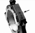
4. The size group number of standard connecting rod bearing shells is stamped on the connecting rod cap.
All Bearings
5. The final and decisive step when selecting new connecting rod and main bearings is checking the clearance with the crankshaft journals. If there are any doubts about the parts being selected, consult the parts supplier or a dealer service center.
Test yourself
A quick Toyota Corolla quiz: every answer comes with an explanation and a link to the manual page.