Piston and Connecting Rod Assembly Installation

Piston ring end gap positioning for 1.3 L engines 1. Top compression ring (number 1)
2. Oil control ring expander
3. Toward the front of the engine
4. Oil control ring lower rail
5. Lower compression ring
6. Oil control ring upper rail
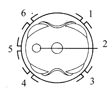
Piston ring end gap positioning for 1.6 and 1.8 L engines 1. Compression ring number 1
2. Piston orientation mark
3. Oil control ring lower rail
4. Compression ring number 2
5. Oil control ring expander
6. Oil control ring upper rail
Before installing the pistons with connecting rods, the cylinder bore walls must be perfectly clean, the cylinder edges must be chamfered, and the crankshaft must be installed in the cylinder block.
PROCEDURE
1. Remove the bearing cap from the connecting rod of the first cylinder (align with the marks made during disassembly). Remove the old connecting rod bearing shells and wipe the mating surfaces of the shells in the connecting rod and the cap with lint-free cloth. These surfaces must always be perfectly clean.

2. Wipe the back of the upper connecting rod bearing shell and seat it in the connecting rod. Make sure the tab on the shell engages the recess in the connecting rod and the oil holes are aligned.
3. Do not use a hammer to install the bearing shell. Use extreme care to avoid damaging the bearing surface. Do not lubricate the bearing shell at this stage.
4. Wipe the back of the lower bearing shell and place it in the connecting rod cap. Again make sure the tab on the shell aligns with the recess in the cap. Do not lubricate the bearing shell. It is very important that the mating surfaces of the bearing shell and connecting rod are perfectly clean and free of oil during assembly.
5. Position the piston ring end gaps according to the figures Piston ring end gap positioning for 1.3 L engines and Piston ring end gap positioning for 1.6 and 1.8 L engines.
6. Slip pieces of rubber hose over the connecting rod cap bolts to protect the cylinder bore from damage.
7. Lubricate the pistons and rings with clean engine oil, and install the ring compressor on the piston. The length of the piston skirt protruding from the compressor should be approximately 6.0 mm to ensure correct entry of the piston into the bore. The rings must be flush with the piston surface.
8. Turn the crankshaft to bottom dead center for the first cylinder, and lubricate the cylinder walls with engine oil.
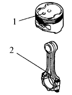
9. Turn the piston and connecting rod so that the marks (1) on the connecting rod and (2) on the piston crown face toward the front of the engine. Carefully insert the piston and connecting rod into the first cylinder until the ring compressor tool contacts the cylinder block.
10. Lightly tap the top edge of the sleeve to ensure even contact with the cylinder block surface around its entire circumference.
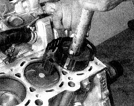
11. Carefully tap the bottom of the piston with the wooden handle of a hammer, guiding the connecting rod onto the corresponding crankshaft journal. The piston rings may pop out of the ring compressor just before entering the cylinder, so the compressor must always be held against the cylinder block.
12. Perform this operation carefully. Stop pushing the piston immediately if any resistance is felt when entering the cylinder. Determine the cause of the piston sticking and eliminate it, then continue installing the piston into the cylinder.
* Do not apply force when installing the piston into the cylinder, regardless of the cause of the resistance. Otherwise, the rings or the piston may be broken.
13. After installing the piston into the cylinder, measure the clearance between the connecting rod bearing and the crankshaft journal, and only then finally install the connecting rod cap.
Checking Connecting Rod Bearing Clearance

14. Prepare a piece of Plastigage, slightly shorter than the width of the connecting rod bearing, and place it on the connecting rod journal (indicated by the arrow) of the first cylinder, parallel to the crankshaft axis.
15. Clean the surface of the connecting rod cap that contacts the bearing shell, remove the hoses from the cap bolts, and install the cap. Make sure the alignment marks on the cap and the connecting rod are on the same side. Make sure the front mark on the cap points toward the timing belt.
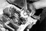
16. Lightly lubricate the contact surfaces of the nuts, install the nuts, and tighten them to the specified torque. Use a socket with a suitable outer diameter to tighten the nuts. This prevents an incorrect torque reading if the socket contacts the connecting rod cap.
17. If the socket begins to contact the cap, lift the socket so that it can rotate freely. Do not rotate the crankshaft while tightening the nuts.
* On 1.6 and 1.8 L engines, after tightening the nuts, turn them an additional 90°.
18. Remove the nuts and carefully remove the caps, taking care not to damage the plastic gauge.

19. Compare the width of the crushed Plastigage with the scale printed on the gauge packaging and determine the oil clearance (the scale is graduated in millimeters and inches). Compare the obtained value with the specification.
20. If the clearance does not match the specification, the cause may be incorrect selection of connecting rod bearings (in this case, select new bearing shells). Before deciding to replace the shells, make sure there was no dirt or oil between the bearings and the connecting rod and cap surfaces during measurement. Also check the diameter of the connecting rod journals. If the width of the crushed Plastigage differs significantly at the ends, the crankshaft main journal is tapered (see subsection 3.1.2.13).
Final Installation of Connecting Rods
21. Carefully remove the remaining Plastigage from the connecting rod journals and/or the connecting rod bearing surfaces. Do not damage the bearing surfaces; scrape with your index finger or the edge of the plastic gauge card.
22. Make sure the working surfaces of the connecting rod bearings are completely clean, then apply a thin, even layer of molybdenum disulfide grease or engine assembly oil to the bearing shells. To access the surface of the upper connecting rod bearing shell, push the piston into the cylinder after first placing pieces of hose over the cap bolts.
23. Pull the connecting rod onto the crankshaft journal, remove the hoses from the cap bolts, install the caps, and tighten the nuts to the torque specified in subsection 3.1.2.1.
24. Repeat the described procedure for the pistons and connecting rods of the remaining cylinders. During assembly, keep the mating surfaces of the connecting rod and the outer surfaces of the connecting rod bearing shells clean. Make sure each piston assembly with connecting rod is installed in its own cylinder. When installing the piston into the cylinder, the recess or arrow must face the front of the engine. Lubricate the cylinder with fresh oil. After measuring the clearance, lubricate the working surfaces of the connecting rod bearings.
25. After final installation of the pistons with connecting rods, check that the crankshaft turns freely by rotating it several revolutions by hand.
26. At the final stage of assembly, check the connecting rod axial play. The check procedure is described in subsection 3.1.2.9.
27. Compare the axial play value with the specification given in subsection 3.1.2.1.
If the axial play was within specification before engine disassembly, and the original crankshaft and connecting rods are reinstalled during repair, the axial play must also be within specification after repair. If new connecting rods and crankshaft are installed, the play may be out of specification. In this case, remove the connecting rods and take them to an automotive workshop for grinding.
Test yourself
A quick Toyota Corolla quiz: every answer comes with an explanation and a link to the manual page.