Connecting Rod and Piston Assembly
* Before removing the piston and connecting rod assemblies, remove the cylinder head, oil pan and oil level gauge tube (refer to subsection 3.1.1.11 and subsection 3.1.1.12).
Removal
PROCEDURE

1. Check the cylinder wall with a fingernail for a ridge formed by piston ring wear at the top of the cylinder (approximately 6.0 mm from the top edge of the cylinder). Remove any ridge caused by carbon buildup or wear with a ridge reamer. Read the manufacturer's instructions supplied with the tool. If this operation is not performed, the piston may be damaged when removing the piston and connecting rod assembly from the cylinder.
2. After removing the ridge, rotate the engine so that the crankshaft is facing up.
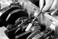
3. Before removing the connecting rods, check their side clearance using a set of feeler gauges. Insert the feeler gauge between the connecting rod and the crankshaft, selecting feeler gauge thickness until the clearance is eliminated. The side clearance is equal to the total thickness of the feeler gauges at which the clearance disappears. If the connecting rod side clearance exceeds the specified value, replace the connecting rod.
4. Measure the side clearance of the other connecting rods in exactly the same way. If new connecting rods (or a new crankshaft) are installed, the side clearance may be below the specification (in this case the connecting rods must be machined; consult an automotive service workshop if necessary). Repeat the procedure for the remaining connecting rods.
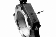
5. Check for marks on the connecting rods and connecting rod caps. If marks are absent, punch them so that the number of punch marks corresponds to the number of the cylinder in which the connecting rod is installed. Marks indicated by an arrow refer to the bearing size group of the connecting rod bearing, not to the connecting rod sequence number!
6. Loosen the nuts by turning them 1/2 turn at a time, until the nuts can be turned by hand. Remove the cap from the connecting rod of the first cylinder together with the connecting rod bearing shell. Do not remove the connecting rod bearing shell from the cap.
* On 1.3 and 1.6 L engines, the connecting rod bolts are pressed into the connecting rod body, and the caps are secured with nuts; on 1.8 L engines, the caps are secured with bolts that screw into the connecting rod body.
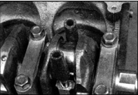
7. Install lengths of rubber or plastic hose over the connecting rod cap bolts to avoid damaging the crankshaft journal and cylinder walls when removing the connecting rod.
8. Push the piston together with the connecting rod and upper connecting rod bearing shell out through the top of the cylinder. Use a wooden block placed against the upper connecting rod bearing shell. If resistance is felt when the piston is pushed out, check again that the ridge at the top of the cylinder has been completely removed.
9. Repeat the procedure for all remaining cylinders.
* When removing the piston and connecting rod from the cylinder, rotate the crankshaft so that the connecting rod remains parallel to the cylinder walls. Do not attempt to remove the piston when the corresponding crankshaft journal is at a large angle to the cylinder axis.
10. After the pistons and connecting rods have been removed from the cylinders, reinstall the connecting rod caps with their bearing shells and tighten the nuts by hand. Until assembly, keep the bearing shells in their original positions to prevent accidental damage to the inner surfaces of the connecting rods and connecting rod caps.
11. Do not separate the pistons from the connecting rods (more detailed information is given below).
Inspection
Before inspection, clean the connecting rods and pistons and remove the old rings from the pistons.
* Old piston rings must always be replaced when the engine is disassembled.
PROCEDURE
1. Carefully remove the rings from the piston using a special piston ring expander. Do not damage the piston surfaces when removing the rings.
2. Scrape carbon from the piston crowns. After removing the heavy upper layer of carbon, clean the piston crown with a brush or cloth-backed abrasive paper. Never remove the remaining carbon with a wire brush mounted on an electric drill, as this may cause erosion of the soft alloy from which the pistons are cast.
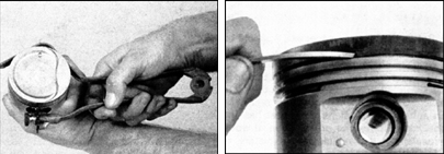
3. Remove carbon from the piston ring grooves using a special tool (photo left). If this tool is not available, use an old broken piston ring (photo right). Remove only carbon, taking care not to remove piston material. Try not to damage the ring groove surfaces.
4. After removing carbon, thoroughly wash the ring groove surfaces with solvent and dry thoroughly with compressed air (if available). Make sure the drain oil slots at the oil control ring location and the oil hole in the connecting rod are clean.
5. If there are no signs of significant wear and cylinder boring is not required, the pistons should not be replaced. Normal wear appears as even vertical wear marks on the piston running surface and as slight loosening of the top compression ring fit. However, replacing the piston rings is mandatory during engine overhaul.
6. Carefully check the piston skirt, piston pin bosses and piston ring lands for cracks.
7. Check the piston skirt running surface for chips and scuffing, for burn-through in the center of the piston crown, and for burning at the piston edges. Chips and scuffing indicate frequent engine overheating, one cause of which may be abnormal fuel-air combustion. In this case, thoroughly check the lubrication and cooling systems. Burn-through in the piston crown indicates operation with incorrect ignition timing. Burning at the edges of the piston crown is usually caused by abnormal combustion (detonation). If these defects are found, determine and eliminate their cause; otherwise abnormal wear may recur. Causes of abnormal engine operation may include air leaks in the intake manifold, incorrect ignition timing, and failure of the exhaust gas recirculation system.
8. Small pits (pitting) corrosion on the piston indicates coolant leaking into the combustion chamber (and into the crankcase). Again, determine the cause and eliminate it; otherwise corrosion will appear in the rebuilt engine.
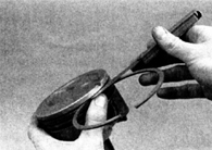
9. Measure the clearance between the ring groove land and the piston ring. Insert a new ring into the groove and slide a feeler gauge between the groove land and the ring.
10. Check the clearance at three or four locations around the full circumference of the groove. Make sure the ring matches the groove it will be installed in, as rings have different thicknesses. If the clearance exceeds the specified limit, replace the piston.

11. Check the piston-to-cylinder clearance by measuring the cylinder bore (refer to Subsection 3.1.2.11) and the piston diameter. Make sure the measurements are taken on a matched pair of parts. Measure the piston diameter at the skirt, in the direction perpendicular to the piston pin axis.
12. The clearance is determined as the difference between the cylinder bore diameter and the piston skirt diameter. If the clearance exceeds the specified limit, the cylinder block must be bored, and the pistons and rings must be replaced with oversize parts.
13. Check the clearance between the piston pin and the connecting rod small end by rocking the piston and the connecting rod in opposite directions. Noticeable play indicates excessive clearance and the need to repair this joint.
14. If it is necessary to remove the pistons from the connecting rods to replace the pistons, or to eliminate piston pin play, take them to an automotive service shop. The connecting rods must also be checked for bend and twist, and the pistons must then be replaced.
15. Check the connecting rods for cracks and other damage. At this stage, remove the connecting rod bearing caps, take out the bearings, wipe the bearing mating surfaces on the cap and the connecting rod, and check for cracks, scratches and scoring. After inspection, assemble the connecting rod, reinstalling the used bearings, and tighten the nuts by hand.
* If engine repair was necessitated by heavy knocking in the connecting rods, the connecting rods must be replaced.
Test yourself
A quick Toyota Corolla quiz: every answer comes with an explanation and a link to the manual page.