Cylinder Head
* New and remanufactured cylinder heads are supplied by the manufacturer as service parts. Because disassembly and inspection procedures require specialized tools, and service parts can sometimes be difficult to obtain, it is more practical to purchase a new cylinder head than to disassemble, inspect and repair the used cylinder head.
Disassembly
PROCEDURE
1. To disassemble the cylinder head, remove the intake and exhaust valves and related components. The procedures below assume that the camshafts and tappets have already been removed (see Subsection 3.1.1.9).

2. Before removing the valves, label them or prepare a place to lay out all valve components together so they can be reinstalled in their original positions.
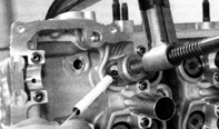
3. Compress the first valve spring using a suitable tool and remove the keepers using a small magnetic screwdriver or special pliers. Carefully release the valve spring, then remove the spring retainer, spring, and spring seat (if equipped).
Warning
When compressing the springs, do not scratch or damage the internal bores for the tappets.
If the spring compressor adapter does not have a side opening for keeper removal, an adapter is available for use with the standard tool.
4. Remove the valve from the valve guide, then remove the valve stem seal. If the valve is difficult to remove from the guide (valve does not pass through), push it back into the guide and lightly file or stone the valve stem near the keeper groove.
5. Repeat the same procedure for the remaining valves. Keep all valve components together so they can be reinstalled in their original positions without mixing their order.
6. After removing the valves and sorting them together with their components, thoroughly clean the cylinder head and inspect its condition. If a complete engine overhaul is being performed, complete all engine disassembly operations before starting cleaning and inspection of the cylinder head.
Thorough cleaning of the cylinder head(s) and valvetrain components followed by inspection will allow you to assess the scope of valve and valvetrain repair work during engine overhaul.
Warning
If the engine has frequently overheated, the cylinder head may be distorted (see below).
Cleaning
PROCEDURE
1. Remove all gasket material residue from the mating surfaces of the cylinder head, cylinder block, intake manifold, and exhaust manifold, taking care not to damage the surfaces. Commercially available gasket remover solvents may be used for this purpose to ease the work.
2. Remove scale deposits from the coolant passages.
3. Remove all deposits from the oil passages using a stiff wire brush. If the coolant passages are heavily corroded, have the cylinder head cleaned at a specialist workshop.
4. Chase the threads in each threaded hole with a tap to remove corrosion and sealant residue. If compressed air is available, blow out all passages and holes to remove debris left after chasing the threads.
5. Clean the threads of the intake and exhaust manifold studs with a stiff wire brush.
6. Wash the cylinder head with solvent and dry thoroughly. Compressed air speeds drying and allows cleaning of all passages, hidden cavities, and holes.
* When cleaning the cylinder head and valvetrain components, carbon remover solvents give very good results. These are highly caustic liquids and must be used with appropriate safety precautions. Read the instructions on the label carefully.
7. Thoroughly clean the tappets by washing them with solvent and drying. Compressed air speeds drying and allows cleaning of the oil passages. Do not mix up the tappets during cleaning; store them in a rack with numbered compartments.
8. Wash all valve springs, keepers, retainers, and spring seats with solvent and dry them thoroughly. Clean the components of one valve at a time to avoid mixing them up.
9. Scrape all deposits from the valves. Then, using a wire wheel mounted on an electric drill, remove carbon from the valve heads and stems. Take care to avoid mixing up the parts.
Inspection
* Before deciding whether parts need regrinding in a workshop, be sure to carry out all procedures described below. Make a list of items requiring special close attention. The procedure for checking tappets and camshafts is described in (see subsection 3.1.1.9).
PROCEDURE
Cylinder Head
1. Carefully inspect the head and check for cracks, signs of coolant leakage, and other damage. If cracks are found, check the cylinder head at a workshop to determine whether it can be repaired. If repair is not possible, replace the cylinder head.
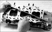
2. Check the cylinder head gasket surface for flatness using a feeler gauge and a straightedge. When measuring, use a feeler gauge with a thickness equal to the specified flatness tolerance. If the distortion exceeds the limit specified in subsection 3.1.2.1, the cylinder head must be resurfaced at an automotive service workshop.
3. Check the condition of the valve seats in each combustion chamber. If pitting, cracks, or burn marks are present, the cylinder head requires repair at an automotive service workshop; this repair cannot be performed at home and is not described in this manual.
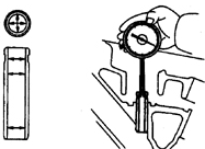
4. Check the clearance between the valve stems and valve guides. Measure using a small-bore gauge and micrometer, or a small-hole dial bore gauge. Guide clearance can also be determined by the side play of a valve stem inserted into the guide, with the valve protruding from the seat by approximately 1.5 mm.
5. Measure play using a dial indicator. To determine the play, divide the total valve movement, measured by the indicator while rocking the valve in the guide, by two. If the clearance exceeds the specification, replace the guide. If after measurement you suspect excessive guide wear and the result seems doubtful, contact an automotive service center, where a more precise measurement can be made for a reasonable fee.
* Most car owners do not have a precision small hole gauge; this tool is available at any local workshop.
Valves
6. Carefully inspect the valves. Check the valve faces for cracks, uneven wear, metal loss and burning. Check the neck and stem for cracks. Check the stems for galling and chipping, and check for bent stems by rotating the valve in the guide. Check the wear of the stem ends. If any of these defects are found, the valves must be repaired at an automotive service workshop.
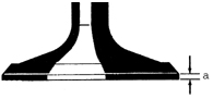
7. Measure the valve margin width (a) of each valve and compare it with the specification. If the margin is less than the specified value, replace the valve.
Valve Train Components
8. Check each valve spring for signs of wear and pitting on the spring ends.
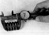
9. Measure the free length of the spring using a vernier caliper with a depth gauge or a dial indicator, and compare it with the specification. Replace springs with set whose free length is less than specified.
10. Before installing the springs on the rebuilt engine, check them under load on a special spring tester (this check must be performed at an automotive service workshop).
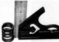
11. Place the spring on a flat, level surface and check it for squareness. If the spring is out of square or bowed along its length, replace it.
12. Check the spring retainers and keepers for visible wear and cracks. Replace any parts that are in doubt, as their failure during engine operation will cause serious damage.
13. If inspection shows that valve components are damaged or worn beyond the limit, replace these parts.
14. If inspection shows that component wear exceeds the limit and the overall condition is unsatisfactory, which is typically the case in engines that have undergone major overhaul, assemble the valves on the cylinder head and follow the recommendations in subsection 3.1.2.8.
Assembly
Before starting assembly, make sure the cylinder head is clean, regardless of whether the head was repaired at an automotive service workshop or not. Note that the cylinder head has several removable plugs designed to relieve stresses in the head material caused by thermal expansion (or contraction). These plugs must be replaced during engine overhaul as well as during cylinder head repair (the replacement procedure is described in subsection 3.1.2.11). If the cylinder head was sent to a workshop for valve repair, the valves will already be installed with all their components. In this case, start assembly from step 7.
PROCEDURE
1. Press new valve stem seals onto the valve guides.
* The valve stem seals for intake and exhaust valves are color-coded differently. Do not mix up these parts during assembly!

2. Install the valve stem seal (indicated by the arrow) onto the valve guide by tapping lightly with a hammer on the installer tool.
* Do not strike the seal after it is fully seated on the guide, otherwise the seal may be damaged. Avoid rotating the seal during installation and keep it evenly seated on the guide; otherwise a reliable seal of the valve stems will not be ensured.
3. Lubricate the valve stem with engine oil or molybdenum disulfide grease and install the first valve, starting from any edge of the cylinder head.
4. Install the spring seat washer (or washers), the valve spring and the spring retainer.
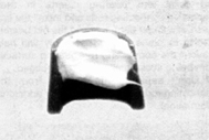
5. Compress the valve spring with the special tool and install the keepers into the groove on the valve stem. Carefully release the spring and make sure the keepers have seated in the upper groove of the valve stem. If necessary, before releasing the valve spring, lubricate the keepers with grease to hold them temporarily on the valve stem.
6. Repeat all steps for the remaining valves. Make sure each valve component is installed in its original position; do not mix up the parts!
7. After installing the valves, check the installed spring height using a vernier caliper with a depth gauge or a dial indicator.
Test yourself
A quick Toyota Corolla quiz: every answer comes with an explanation and a link to the manual page.