Signals for the control unit
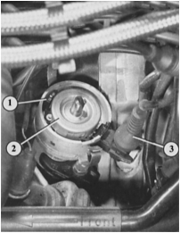
Open distributor (example of 4-cylinder engine):
1 – Hall sender;
2 – trigger wheel;
3 – Hall sender connector.
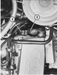
On the 6-cylinder engine the Hall sender is located far back, behind the left cylinder head:
1 – Hall sender housing;
2 – connector.
Hall sender
The switching on and off of the current to the ignition coil mentioned in the last section is provided (also via the control unit and electronic switch – see below) by the Hall sender. On 4- and 5-cylinder models it is located in the distributor, and on 6-cylinder models at the rear of the left cylinder head.
Its name has nothing to do with large halls etc. It is related to the name of the discoverer of the Hall effect, which is used in the operation of this sender.
The Hall sender is located at the bottom of the distributor housing and consists of the following elements: trigger wheel (rotor) with 4, 5 or 6 slots (depending on the number of cylinders), a permanent magnet, and the Hall integrated circuit located opposite it. Together they work roughly like a photoelectric relay, except that magnetic fields act instead of light.
This becomes completely clear if we imagine an automatic elevator door. If you stand in the doorway and interrupt the light beam, the elevator door stays open. As soon as you step away and let the light through again, the door mechanism receives the command to close.
Returning to the ignition system: if the trigger wheel vane is in the magnetic field, the Hall sender passes current to the control unit. If the vane leaves the gap between the Hall integrated circuit and the permanent magnet, no power is supplied to the control unit. These are the pulses that control ignition.
Note: the slots in the distributor trigger wheel are arranged so that the signal pulse, for example on a 4-cylinder engine, reaches the control unit 60° before TDC. During this time the control unit calculates the optimal ignition timing based on engine speed information (from the sequence of signal pulses) and engine load (from the air flow meter resistance, throttle potentiometer or intake manifold pressure sensor signals).
Engine speed sender and ignition timing sender
6-cylinder models
In addition to the Hall sender, 6-cylinder engines are equipped with an engine speed sender and an ignition timing sender. Both are so-called inductive senders.
The speed sensor works as follows: the sensor contains a coil and a magnet. They interact with the toothed projections on the flywheel at the rear of the crankshaft. Each time a tooth passes under the sensor, the magnetic field of the permanent magnet changes, and a voltage is induced in the coil. This small signal is sufficient for processing by the MPI/MPFI engine control unit. In this way, information about the crankshaft speed is supplied.
To detect the exact crankshaft position, a steel pin is installed at one specific point on the flywheel. When it passes under the sensor, a voltage peak occurs, which the control unit uses to determine the position.
Test yourself
A quick Audi 80 quiz: every answer comes with an explanation and a link to the manual page.