KE-III-Jetronic Injection System
Main Components
In this manual: KE-III-Jetronic Injection System
~1min read
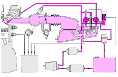
Operating diagram of the KE-III-Jetronic injection system. Fuel is shown in red, incoming air is shown in light pink.
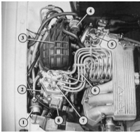
View of KE-III-Jetronic fuel mixture control unit
1 – pressure regulator;
2 – control plate potentiometer;
3 – air intake hose;
4 – activated charcoal canister solenoid valve;
5 – throttle lever;
6 – high-pressure fuel line;
7 – fuel distributor;
8 – pressure regulator.
To better understand the complete operation of the injection system, the key components and concepts must first be explained:
Test yourself
A quick Audi 80 quiz: every answer comes with an explanation and a link to the manual page.
Was this page helpful?