Performance Check
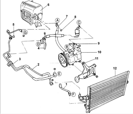
Air Conditioning System Components
1 – tube (A);
2 – tube (B);
3 – discharge tube;
4 – discharge tube;
5 – high-pressure port;
6 – evaporator unit;
7 – tube;
8 – nut, 5–7 N·m;
9 – low-pressure port;
10 – compressor;
11 – compressor bracket;
12 – condenser;
A – evaporator to suction tube, 5–7 N·m;
B – suction tube to compressor, 8–12 N·m;
C – compressor discharge hose, 17–26 N·m;
D – discharge hose to discharge tube, 19–28 N·m;
E – discharge tube to condenser, 19–28 N·m;
F – tube (A) to condenser, 7–11 N·m;
G – tube (B) to evaporator, 12–15 N·m.

Air Conditioning Circuit
PROCEDURE
1. Install the manifold gauge set on the line.
2. Start the engine and run it at 2000 min⁻¹, then set the maximum cooling mode with high fan speed.
3. Open all windows or doors.
4. Install a thermometer in the passenger compartment air outlet grille.
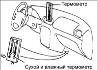
5. Install the wet and dry bulb thermometers as close as possible to the inlet of the cooling unit.
6. Check that the pressure shown on the gauge is within 1.373–1.575 kPa. If the pressure is too high, pour water on the condenser. If the pressure is too low, cover the front of the condenser.
7. Check that the air temperature at the air outlet grille to the passenger compartment is within 25–35 °C.
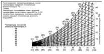
8. Using the chart, determine the relative humidity by comparing the wet bulb and dry bulb temperatures.
9. Measure the temperature at the air outlet grille to the passenger compartment, and calculate the difference between the dry bulb thermometer and the thermometer at the air outlet grille.
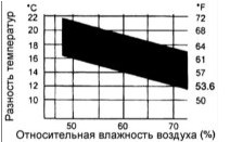
10. Check that if the intersection of relative humidity and temperature difference is within the tolerance, the air conditioning system is operating normally.
Test yourself
A quick Hyundai Accent quiz: every answer comes with an explanation and a link to the manual page.