Brush Replacement
PROCEDURE
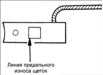
1. If the brushes are worn to the minimum allowable length, replace them.
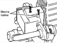
2. Unsolder the braided wire and remove the spring and brush.
3. Install the brush spring and a new brush into the brush holder.
4. Insert the brush so that there is a clearance of 2–3 mm between the wear limit line and the end of the brush holder.
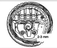
5. Solder the braided wire to the brush holder.
Disassembly (90 A)
PROCEDURE
1. Remove the nuts securing the "B" terminal to the rear cover.
2. If it is necessary to remove the stator, unsolder the four stator wires from the rectifier diodes.
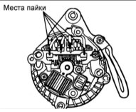
Perform soldering for no more than 5 seconds, otherwise the rectifier diodes may be damaged.
3. Remove the stator from the rear cover.
4. Remove the brush holder and the rectifier.
5. Remove the four through bolts.
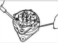
6. Insert the blades of two flat-blade screwdrivers between the front cover and the stator core, and remove the cover.

Do not insert the screwdrivers too deeply, as the stator winding may be damaged.
The rear cover may be difficult to remove because a ring retains the outer race of the rear bearing. To ease removal of the rear cover, heat it with a 200 W soldering iron. Do not use a hot air gun for heating, as the diode assembly may be damaged.
7. Secure the rotor in a vise on the pulley side.
Install soft protective pads on the vise jaws to prevent damage to the generator parts.
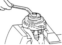
8. Remove the pulley nut, then remove the spring washer, pulley, and spacer sleeve.
9. Remove the front cover and washers.
10. Remove the rotor from the vise.
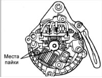
11. When separating the rectifier from the brush holder, unsolder the two plates from the rectifier.
Inspection (90 A)
Rotor
PROCEDURE
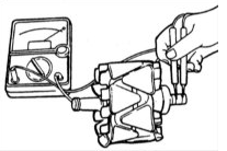
1. Using an ohmmeter, measure the resistance between the slip rings. If the resistance is extremely low, there is a short circuit in the rotor winding. If there is no continuity, there is an open circuit in the rotor winding; replace the rotor.
Resistance: 3.1 Ohms
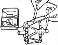
2. Using an ohmmeter, check for continuity between the slip ring and the rotor core. If there is continuity, replace the rotor.
Stator
PROCEDURE

1. Using an ohmmeter, check for continuity between the stator coil wires. If there is no continuity, replace the stator.
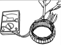
2. Using an ohmmeter, check for continuity between the stator coils. If there is continuity, replace the stator.
Rectifier Assembly Inspection
PROCEDURE
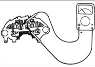
1. Check for continuity between the positive rectifier terminals and the stator coil output terminal. The ohmmeter should show continuity in one direction only. If continuity exists in both directions, a diode is broken down and the rectifier must be replaced.
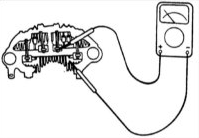
2. Check for continuity between the negative rectifier terminals and the stator coil output terminal. The ohmmeter should show continuity in one direction only. If continuity exists in both directions, a diode is broken down and the rectifier must be replaced.

3. Using an ohmmeter, check for continuity between the terminals of each of the three diodes. The ohmmeter should show continuity in one direction only. If continuity exists in both directions, a diode is broken down and the rectifier must be replaced.
Test yourself
A quick Hyundai Accent quiz: every answer comes with an explanation and a link to the manual page.