Engine Control System/Fuel System
Engine Control Module (ECM)
In this manual: Engine Control System/Fuel System
13steps
~78min
3/5difficulty
Done 0 of 13
Circuit Diagrams
ECM Terminal and Input/Output Signal [M/T]
1. Harness Connector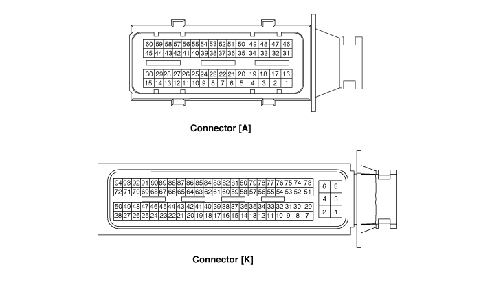
| Pin No. | Description |
| 1 | Ignition Coil Control Output (Cylinder #3) |
| 2 | Ignition Coil Control Output (Cylinder #2) |
| 3 | - |
| 4 | Electronic Wastegate Actuator (EWGA) Motor [+] Control Output |
| 5 | Injector (Cylinder No. 3) [Low] Control Output |
| 6 | - |
| 7 | Engine Coolant Temperature Sensor (ECTS) Signal Input |
| 8 | - |
| 9 | Boost Pressure Sensor (BPS) Input Signal |
| 10 | - |
| 11 | - |
| 12 | Electronic Wastegate Actuator (EWGA) Feedback Signal Input |
| 13 | Throttle Position Sensor (TPS) 1 Signal Input |
| 14 | Accelerator Pedal Position Sensor (APS) 1 Signal Input |
| 15 | Brake Booster Vacuum Pressure Sensor (BBVPS) Signal Input |
| 16 | - |
| 17 | Ignition Coil Control Output (Cylinder No. 1) |
| 18 | ETC Motor [+] Control Output |
| 19 | Electronic Wastegate Actuator (EWGA) DC Motor [-] Control Output |
| 20 | Injector (Cylinder No. 2) [Low] Control Output |
| 21 | Wiper Switch Signal Input |
| 22 | Neutral Switch Input Signal |
| 23 | - |
| 24 | Camshaft Position Sensor (CMPS) [Bank 1/Exhaust] Signal Input |
| 25 | A/C Dual Pressure Switch Signal Input |
| 26 | Vehicle Speed Signal Input |
| 27 | Start Signal Input |
| 28 | Brake Check Switch Input Signal |
| 29 | Stop Lamp Switch Input Signal |
| 30 | Clutch Switch Signal Input |
| 31 | Injector (Cylinder No. 2) [High] Control Output |
| 32 | Injector (Cylinder No. 3) [High] Control Output |
| 33 | - |
| 34 | Injector (Cylinder No. 1) [Low] Control Output |
| 35 | Fuel Pressure Control Valve (FPCV) [High] Control Output |
| 36 | Camshaft Position Sensor (CMPS) [Row 1/Intake] Ground |
| 37 | Camshaft Position Sensor (CMPS) [Row 1/Exhaust] Ground |
| 38 | - |
| 39 | - |
| 40 | - |
| 41 | Heated Oxygen Sensor (HO2S) [Bank 1/Sensor 2] Input Signal |
| 42 | - |
| 43 | Battery Sensor Temperature Signal Input |
| 44 | ISG OFF Switch Input Signal |
| 45 | Electrical Load Input Signal [Defrost] |
| 46 | - |
| 47 | Injector (Cylinder No. 1) [High] Control Output |
| 48 | ETC Motor [-] Control Output |
| 49 | - |
| 50 | Fuel Pressure Control Valve (FPCV) [Low] Control Output |
| 51 | Wheel Speed Sensor Signal Input [A] |
| 52 | Wheel Speed Sensor Signal Input [B] |
| 53 | Crankshaft Position Sensor (CKPS) Ground |
| 54 | Crankshaft Position Sensor (CKPS) Signal Input |
| 55 | - |
| 56 | Camshaft Position Sensor (CMPS) [Bank 1/Intake] Signal Input |
| 57 | Heated Oxygen Sensor (HO2S) [Row 1/Sensor 2] Ground |
| 58 | - |
| 59 | Battery Sensor Current Direct Signal Input |
| 60 | - |
[Connector B]
| Pin No. | Description |
| 1 | ECM Ground |
| 2 | ECM Ground |
| 3 | ECM Ground |
| 4 | Battery Power (B+) |
| 5 | Battery Power (B+) |
| 6 | Battery Power (B+) |
| 7 | Battery Power (B+) |
| 8 | Accelerator Position Sensor (APS) No. 1 Ground |
| 9 | Manifold Absolute Pressure and Temperature Sensor (MAPS) Ground |
| 10 | Boost Pressure Sensor (BPS) Ground |
| 11 | - |
| 12 | Electronic Wastegate Actuator (EWGA) Ground |
| 13 | - |
| 14 | - |
| 15 | - |
| 16 | Engine Coolant Temperature Sensor (ECTS) Ground |
| 17 | - |
| 18 | - |
| 19 | - |
| 20 | A/C Compressor Relay Control Output |
| 21 | - |
| 22 | CVVT Oil Control Valve (OCV) [Bank 1/Intake] Control Output |
| 23 | - |
| 24 | Radiator Cooling Fan PWM Control Output |
| 25 | - |
| 26 | - |
| 27 | Fuel Pump Relay Control Output (with Immobilizer/Smart Key) |
| 28 | - |
| 29 | Ignition Switch Input Signal |
| 30 | Accelerator Position Sensor (APS) No. 2 Ground |
| 31 | - |
| 32 | - |
| 33 | Battery Sensor Ground |
| 34 | - |
| 35 | - |
| 36 | Rail Pressure Sensor (RPS) Ground |
| 37 | - |
| 38 | - |
| 39 | - |
| 40 | - |
| 41 | Starter Relay [Low] Control Output |
| 42 | - |
| 43 | Accelerator Position Sensor (APS) No. 2 Power Supply (+5V) |
| 44 | Camshaft Position Sensor (CMPS) Power Supply (+5V) |
| 45 | - |
| 46 | ISG OFF Lamp Output Signal |
| 47 | - |
| 48 | - |
| 49 | - |
| 50 | CVVT Oil Control Valve (OCV) Control Output [Bank 1/Exhaust] |
| 51 | Main Relay Control Output |
| 52 | Throttle Position Sensor (TPS) Ground |
| 53 | Fan Switch MAX Signal Input |
| 54 | - |
| 55 | - |
| 56 | Intake Air Temperature Sensor (IATS) Input Signal |
| 57 | Manifold Absolute Pressure Sensor (MAPS) Signal Input |
| 58 | Knock Sensor (KS) Ground |
| 59 | VS+ (Nernst Cell Voltage) |
| 60 | Rc (Compensation Resistance) |
| 61 | LIN Communication Input Signal |
| 62 | - |
| 63 | C-CAN [Low] |
| 64 | Battery Sensor Power Supply (+5V) |
| 65 | Crankshaft Position Sensor (CKPS) Power Supply (+5V) |
| 66 | Accelerator Position Sensor (APS) No. 1 Power Supply (+5V) |
| 67 | Starter Relay [High] Control Output |
| 68 | RCV Control Solenoid Valve Control Output |
| 69 | - |
| 70 | - |
| 71 | Fuel Pump Relay Control Output (without Immobilizer/Smart Key) |
| 72 | - |
| 73 | - |
| 74 | Throttle Position Sensor (TPS) 2 Signal Input |
| 75 | - |
| 76 | Fuel Level Sensor (FLS) Signal Input |
| 77 | Accelerator Pedal Position Sensor (APS) 2 Signal Input |
| 78 | Rail Pressure Sensor (RPS) Signal Input |
| 79 | Knock Sensor (KS) Signal Input |
| 80 | VS-/IP- (Common Ground for VS, IP) |
| 81 | Rc/Rp (Pump Cell Voltage) |
| 82 | Engine Speed Output Signal |
| 83 | Immobilizer Communication Line |
| 84 | - |
| 85 | C-CAN [High] |
| 86 | Manifold Absolute Pressure Sensor (MAPS) Power Supply (+5V) |
| Electronic Wastegate Actuator (EWGA) Power Supply (+5V) | |
| 87 | Boost Pressure Sensor (BPS) Power Supply (+5V) |
| Rail Pressure Sensor (RPS) Power Supply (+5V) | |
| 88 | ETC Module Power Supply (+5V) |
| 89 | Heated Oxygen Sensor (HO2S) [Bank 1/Sensor 1] Heater Control Output |
| 90 | - |
| 91 | Heated Oxygen Sensor (HO2S) [Bank 1/Sensor 2] Heater Control Output |
| 92 | - |
| 93 | - |
| 94 | Purge Control Solenoid Valve (PCSV) Control Output |
Repair Procedures
Removal
- Turn the ignition switch OFF and disconnect the negative (-) battery terminal.
- Disconnect the battery. (Refer to Engine Electrical System - Battery).
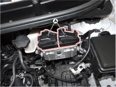
- Disconnect the ECM connectors (A).
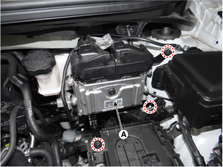
- Remove the mounting bolts and nuts, then remove the engine control module bracket assembly (A). ECM bracket mounting bolt/nut: 9.8–11.8 N·m
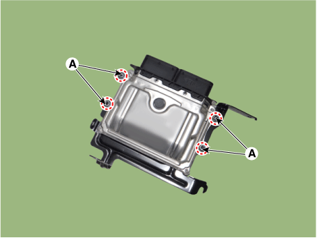
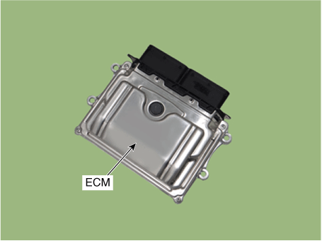
- Remove the ECM by loosening the mounting nuts (A) on the bracket.
ECM mounting nut: 9.8–11.8 N·m
Installation
- Install in the reverse order of removal.
ECM Circuit Inspection Procedure
- ECM GROUND CIRCUIT TEST: Measure the resistance between the ECM ground terminals and chassis ground, using the rear side of the ECM harness connector as the ECM-side checkpoint. Repair any problem found.
Specification: Below 1 Ω
- ECM CONNECTOR TEST: Disconnect the ECM connector and visually check the ECM-side and harness-side ground terminals for bent pins or poor contact pressure. Repair any problem found.
- If the problem cannot be found in steps 1 and 2, the ECM may be faulty. If so, make sure the DTC is not present before replacing the ECM with a new one, then recheck the vehicle. If a DTC is present, troubleshoot it first before replacing the ECM.
- ECM RETEST WITH ORIGINAL ECM: Install the original ECM (suspected faulty) into a known-good vehicle and check the vehicle. If the problem recurs, replace the original ECM with a new one. If the problem does not recur, it is an intermittent problem (Refer to Intermittent Troubleshooting Procedure in Basic Troubleshooting Procedure).
Adjustment
ECM Neutral Mode Procedure
- After replacing the ECM on a vehicle equipped with an immobilizer, perform the following procedure.
| [When Installing Used ECM] |
- Perform the "ECM Neutral Mode" procedure using KDS. (Refer to Body Electrical System - Immobilizer System - Repair Procedures).
- After completing the "ECM Neutral Mode" procedure, perform the "Key Learning" procedure using KDS. (Refer to Body Electrical System - Immobilizer System - Repair Procedures).
| [When installing a new ECM] Perform the "Key Learning" procedure using KDS. (Refer to Body Electrical System - Immobilizer System - Repair Procedures). |
- After replacing the ECM on a vehicle equipped with a smart key system (push button start), perform the following procedure.
| [When Installing Used ECM] |
- Perform the "ECM Neutral Mode" procedure using KDS. (Refer to Body Electrical System - Smart Key System - Repair Procedures).
- After completing the "ECM Neutral Mode", turn the ignition on, then off using the smart key or start button. The ECM will then automatically learn the smart key information.
| [When installing a new ECM] Turn the ignition on and then off using the Smart Key or the start button. The ECM will then automatically receive the Smart Key information. |
- Perform ETC module learning after replacing the ETC module. (Refer to Electronic Throttle Control System - Adjustment).
Test yourself
A quick Kia Picanto JA quiz: every answer comes with an explanation and a link to the manual page.
Was this page helpful?