Catalyst
Exploded View
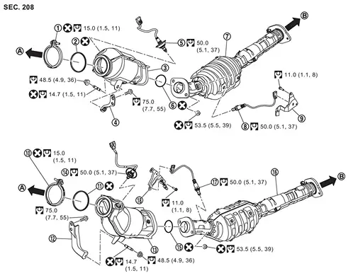
 |
Clamp (bank 1) |  |
Gasket 1 (bank 1) |  |
Catalyst converter (bank 1) |
 |
Catalyst converter support bracket (bank 1) |  |
Air fuel ratio (A/F) sensor (bank 1) |  |
Gasket 2 (bank 1) |
 |
2nd catalyst converter (bank 1) |  |
Heated oxygen sensor (bank 1) |  |
Bracket (bank 1) |
 |
Clamp (bank 2) |  |
Gasket 3 (bank 2) |  |
Catalyst converter support bracket (bank 2) |
 |
Catalyst converter (bank 2) |  |
Air fuel ratio (A/F) sensor (bank 2) |  |
Gasket 4 (bank 2) |
 |
2nd catalyst converter (bank 2) |  |
Heated oxygen sensor (bank 2) |  |
Bracket (bank 2) |
 |
To turbocharger assembly. Refer to Exploded View. |  |
To main muffler. Refer to EXHAUST SYSTEM : Exploded View. | ||
 : Always replace after every disassembly. |
|||||
 : N·m (kg-m, ft-lb) |
|||||
Removal and Installation
REMOVAL
Bank 1 side
Remove front tire assembly (RH). Refer to ROAD WHEEL TIRE : Removal & Installation.
Remove fender protector (RH). Refer to Removal and Installation.
Remove main muffler. Refer to EXHAUST SYSTEM : Removal & Installation.
Remove 2nd catalyst converter (bank 1)  .
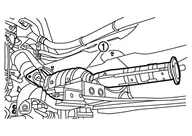
Using the heated oxygen sensor wrench [SST: KV10117100 (NI-3647-A)], remove heated oxygen sensor (bank 1), if necessary.
Remove catalyst converter support bracket (bank 1) from A/T side  .

Remove mounting nut of 12V sub battery (lithium ion battery) harness 1. Refer to Exploded View.
Remove 12V sub battery (lithium ion battery) harness 1 bracket .
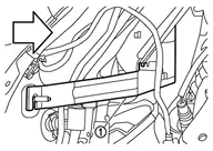
| : vehicle front |
Using the heated oxygen sensor wrench [SST: KV10117100 (NI-3647-A)], remove air fuel ratio (A/F) sensor (bank 1) .
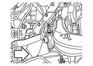
| : vehicle front |
Remove heat insulator (upper). Refer to Removal & Installation.
Remove clamp (bank 1) .
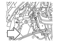
| : vehicle front |
Remove catalyst converter (bank 1).
Bank 2 side
Remove front tire assembly (LH). Refer to ROAD WHEEL TIRE : Removal & Installation.
Remove fender protector (LH). Refer to Removal and Installation.
Remove main muffler. Refer to EXHAUST SYSTEM : Removal & Installation.
Remove 2nd catalyst converter (bank 2) .
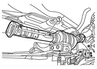
Using the heated oxygen sensor wrench [SST: KV10117100 (NI-3647-A)], remove heated oxygen sensor (bank 2), if necessary.
Remove front propeller shaft (4WD models). Refer to Removal and Installation.
Remove catalyst converter support bracket (bank 2) from A/T side .
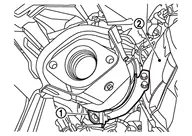
Disconnect the connection between the lower shaft and the lower joint. Refer to Removal and Installation.
Remove heat insulator (upper). Refer to Removal & Installation.
Using the heated oxygen sensor wrench [SST: KV10117100 (NI-3647-A)], remove air fuel ratio (A/F) sensor (bank 2) .
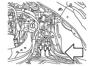
| : vehicle front |
Remove clamp (bank 2) .
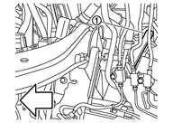
| : vehicle front |
Remove catalyst converter (bank 2).
INSTALLATION
Install in the reverse order of removal.
Clean up on the gasket touching surface.
Temporarily install catalyst converter to turbocharger.
Temporarily install 2nd catalyst converter to catalyst converter.
Temporarily install main muffler to 2nd catalyst converter.
Temporarily tighten the bolt and nut of temporarily-tightened parts.
Temporarily tighten mounting bolt of main muffler .

Temporarily tighten mounting bolts and mounting nuts of catalyst converter (bank 1 and bank 2).
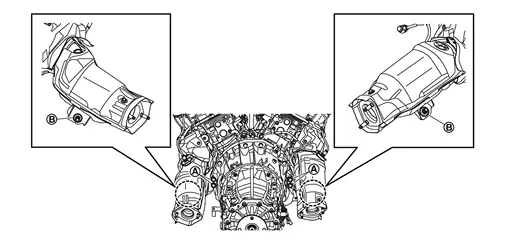
Temporarily install 2nd catalyst converter (bank 1 and bank 2) using the following steps.Temporarily tighten mounting nuts  and
 .
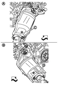
|
: Clamp (bank 1) |
|
: Clamp (bank 2) |
|
: Bank 1 |
|
: Bank 2 |
| : vehicle front |

|
: Bank 1 |
|
: Bank 2 |
Tighten the temporarily tightened bolts and nuts to the specified torque, according to the following step:Tighten clamp (bank 1).
|
: Clamp (bank 1) |
|
: Clamp (bank 2) |
|
: Bank 1 |
|
: Bank 2 |
|
: Nut (bank 1) |
|
: Nut (bank 2) |
| : vehicle front |
and mounting nut of catalyst converter support bracket (bank 1 and bank 2) to specified torque. of main muffler to specified torque. Inspection
INSPECTION AFTER REMOVAL
Surface Distortion
Check the surface distortion of the catalyst converter mating surface (turbocharger side) with a straigtedge (A) and a feeler gauge (B).

Limit 0.15 mm (0.0059 in)
Check the surface distortion of the catalyst converter mating surface (2nd catalyst converter side) with a straigtedge (A) and a feeler gauge (B).
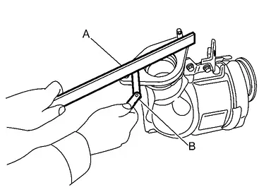
Limit 0.5 mm (0.020 in)
Check the surface distortion of the 2nd catalyst converter mating surface (catalyst converter side) with a straigtedge (A) and a feeler gauge (B).
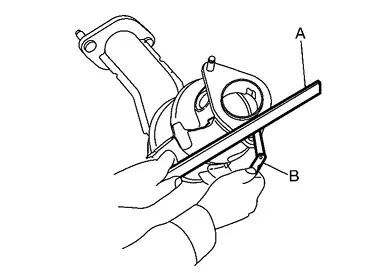
Limit 0.5 mm (0.020 in)