Ignition Coil, Spark Plug and Rocker Cover
Exploded View
Bank 1 side
 |
Ignition coil |  |
Spark plug |  |
Rocker cover |
 |
Rocker cover gasket |  |
Blow-by hose 1 (bank 1) |  |
Clamp |
 |
Blow-by hose 2 (bank 1) |  |
Intake camshaft position sensor |  |
Exhaust camshaft position sensor |
 |
Crankcase pressure sensor | ||||
 |
Comply with the installation procedure when tightening. Refer to Removal and Installation. |  |
Camshaft bracket side |  |
To rocker cover (bank 2). |
 |
To intake manifold. Refer to Exploded View. | ||||
 |
: N·m (kg-m, ft-lb) | ||||
 |
: N·m (kg-m, in-lb) | ||||
 |
: Always replace after every disassembly. | ||||
 |
: Should be lubricated with oil. | ||||
 |
: Sealing point | ||||
 |
: Indicates that the parts is connected at points with same symbols in actual vehicle. | ||||
Bank 2 side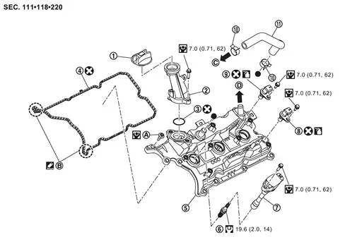
|
Oil filler cap | |
Oil filler tube | |
O-ring |
|
Rocker cover gasket | |
Rocker cover | |
Spark plug |
|
Ignition coil | |
Intake camshaft position sensor | |
Exhaust camshaft position sensor |
|
Clamp |  |
Blow-by hose (bank 2) | ||
|
Comply with the installation procedure when tightening. Refer to Removal and Installation. | |
Camshaft bracket side | |
To air duct. Refer to Exploded View. |
|
To rocker cover (bank 1). | ||||
|
: N·m (kg-m, ft-lb) | ||||
|
: N·m (kg-m, in-lb) | ||||
|
: Always replace after every disassembly. | ||||
|
: Should be lubricated with oil. | ||||
|
: Sealing point | ||||
|
: Indicates that the parts is connected at points with same symbols in actual vehicle. | ||||
Removal and Installation
REMOVAL
Ignition coil
Remove engine cover. Refer to Removal and Installation.
Remove mounting bolt from air inlet tube 1  . (No. 1 and No. 6 cylinder)
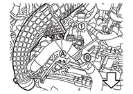
| : vehicle front |
Remove mounting bolt from air inlet tube 1 . (No. 1 and No. 6 cylinder)
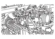
| : vehicle front |
Remove mounting bolt from air inlet tube 1 . (No. 1 and No. 6 cylinder)
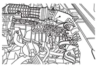
Remove air inlet tube 1 from turbocharger (bank 1 side). (No. 1 and No. 6 cylinder)
Refer to Removal & Installation.
Move air inlet tube 1 to a position where it is easier to work. (No. 1 and No. 6 cylinder)
Remove ignition coil.
Rocker cover
Remove the following parts:
Engine cover: Refer to Removal and Installation.
Air cleaner assembly: Refer to Removal and Installation.
Air inlet tube: Refer to Removal & Installation.
Intake manifold: Refer to Removal and Installation.
Remove bank 1 by following the steps below.Remove ignition coil.
Remove blow-by hose 1 (bank 1) and blow-by hose 2 (bank 1) . 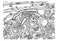 .
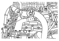 .

Remove bank 2 by following the steps below.Remove crankcase ventilation valve and resonator as a set. Remove blow-by hose (bank 2) .
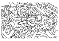
Loosen mounting bolts in the order from 10 to 1 (bank 1 ), and for (bank 2 ), from 11 to 1 as shown in the figure.

| : Engine front |
Remove rocker cover gasket from rocker cover.
INSTALLATION
Apply liquid gasket to the positions shown.
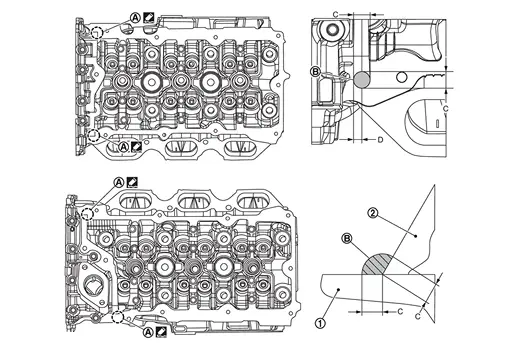
|
: Cylinder head |
|
: Camshaft bracket (No. 1) |
| C | : 10 mm (0.39 in) |
| D | : 4 mm (0.16 in) (Application position of liquid gasket from the end surface of the camshaft bracket) |
Use Genuine RTV Silicone Sealant or an equivalent. Refer to Recommended Chemical Products and Sealants.
Install the rocker cover using the following steps:
Bank 1 side
Install guide pin in the shown figure 9.
| : Engine front | |
|
: Bank 1 side |
|
: Bank 2 side |
Temporarily tighten the mounting bolts in the order shown in figure 1 to 8.
: 2 N·m Remove the guide pin.
Temporarily tighten the mounting bolts in the order shown in figure 9 to 10.
: 2 N·m Tighten to the specified torque in the order 1 to 10 shown in the figure.
: 8.33 N m (0.85 kg-m, 74 in-lb) Bank 2 side
Install guide pin in the shown figure 10.
| : Engine front | |
|
: Bank 1 side |
|
: Bank 2 side |
Temporarily tighten the mounting bolts in the order shown in figure 1 to 9.
: 2 N·m Remove the guide pin.
Temporarily tighten the mounting bolts in the order shown in figure 10 to 11.
: 2 N·m Tighten to the specified torque in the order 1 to 11 shown in the figure.
: 8.33 N m (0.85 kg-m, 74 in-lb)