Fuel Injector and Fuel Tube
Exploded View
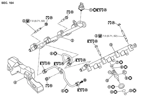
 |
Fuel rail pressure sensor |  |
Fuel rail (bank 1) |  |
Stud bolt |
 |
Fuel tube insulator |  |
Fuel tube 2 |  |
Fuel tube 1 |
 |
O-ring |  |
Backup ring |  |
Injector holder |
 |
Fuel injector |  |
Decoupling element |  |
Spring |
 |
Seal ring |  |
Fuel rail (bank 2) | ||
 |
Comply with the assembly procedure when tightening. Refer to Removal and Installation. |  |
To high pressure fuel pump. Refer to Exploded View. | ||
 : Always replace after every disassembly. |
|||||
 : N·m (kg-m, ft-lb) |
|||||
 : N·m (kg-m, in-lb) |
|||||
 : Should be lubricated with oil. |
|||||
Removal and Installation
REMOVAL
Release fuel pressure. Refer to Work Procedure.
Disconnect battery cable from the negative terminal.
Remove engine cover. Refer to Removal and Installation.
Remove air cleaner assembly. Refer to Removal and Installation.
Remove charge air cooler. Refer to Removal & Installation.
Remove intake manifold. Refer to Removal and Installation.
Remove fuel tube 1 and 2.
Disconnect fuel rail pressure sensor harness connector .
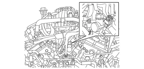
Disconnect fuel injector harness connector.
Remove fuel rail pressure sensor if necessary.
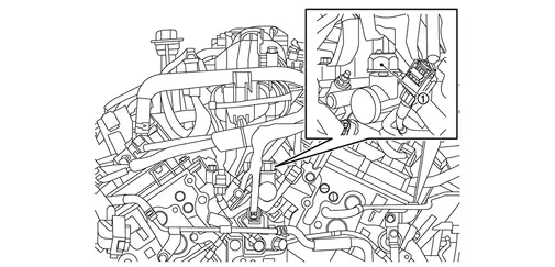
Follow steps below to remove the fuel injector.Remove fuel rail (bank 1) , fuel rail (bank 2) in this order.
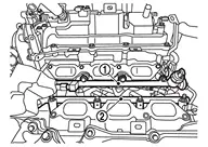 and fuel injector assembly. (bank1 and bank 2)

| : Engine front |
If the fuel rail and fuel injector cannot be removed assembly, follow the steps below to remove them.
Remove fuel injector from cylinder head as per the following.
Remove injector holder.
Install an remover [SST: KV101296S0 ( — )] (A) to the injector connector side so that cutout
of injector remover faces the injector connector side.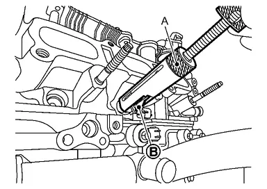
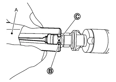
Hook pawl portion
of injector remover [SST: KV101296S0 ( — )] (A) to groove portion  of injector.
Press down body portion of injector remover [SST: KV101296S0 ( — )] (A) until it contacts cylinder head.
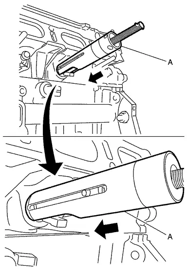
Tighten injector remover [SST: KV101296S0 ( — )] clockwise and remove injector from cylinder head.

Pinch the seal ring
and cut it off. Never scratch the fuel injector.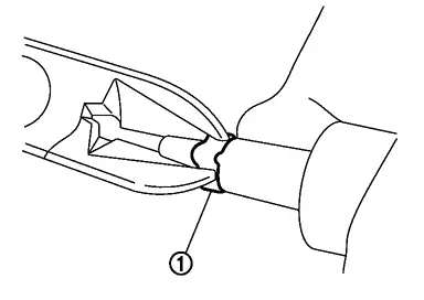
INSTALLATION
After removing fuel pressure sensor, install fuel pressure sensor according to the instructions below:Fix fuel rail in a vice.
Apply engine oil to the entire perimeter of the fuel pressure sensor screw and the tip. Temporarily tighten fuel pressure sensor. |
: 10 N·m |
| Tightening angle : | 35° |
Install seal ring to fuel injector using the following procedure:
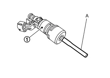
Point the injector mark
side of the injector seal drift [SST:KV10119990 ( — )] (A) in the direction of the fuel injector and insert the injector seal drift in to the fuel injector.
Install seal guide [SST: KV10119990 ( — )] (A) to fuel injector
.
Set seal ring
into seal guide [SST:KV10119990 ( — )] (A).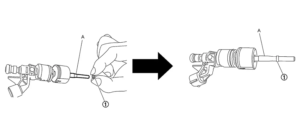
Set seal installer [SST:KV10119990 ( — )] (A) into seal guide [SST:KV10119990 ( — )] (B).
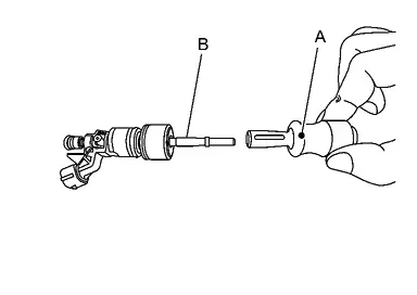
Install seal ring
to the fuel injector by pushing it in, in the direction of the arrow with seal installer (A).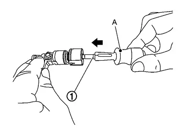
Rotate clockwise and counterclockwise by 90° while pressing seal ring to fit it by injector seal drift [SST:KV10119990 ( — )] (A).
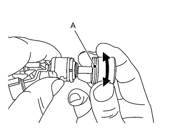
Note the following points and install the O-ring and backup ring to the fuel injector.
Install fuel injector to fuel rail as per the following:
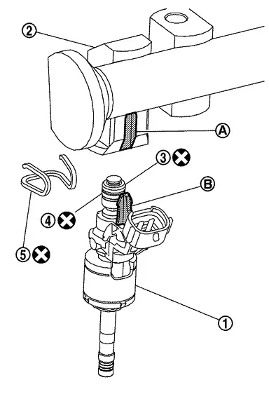
|
: O-ring (black) |
|
: Backup ring |
to fuel injector. Insert fuel injector into fuel rail with fuel injector holder attached. Insert it while matching it to the axial center.
Insert so that protrusion
of fuel injector is aligned to cutout .
Check that protrusions of fuel injectors and fuel rail are aligned with cutouts of clips after installation.
Install the fuel injector (bank1 and bank 2 ) into the cylinder head installation hole.
Tighten mounting bolts and nuts in two steps in the order from 1 to 4 shown in the figure.
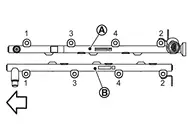
: Engine front 1st step : 10 N·m2nd step : 22 N·m
Connect the fuel rail pressure sensor harness connector.
Connect the fuel injector harness connector.
Install fuel tube according to the following procedure :
Fuel tube 1
Apply engine oil to the following parts.
Contact surface of the high-pressure fuel pump
Contact surface of fuel rail
Temporarily tighten flare nuts fuel tube 1.
Tighten the flare nut
on fuel tube 1 to the specified torque.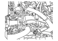
: 15 N·m Tighten the flare nut
on fuel tube 1 to the specified torque.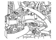
: 15 N·m Tighten the flare nut
on fuel tube 1 to the specified torque.: 38 N·m Tighten the flare nut
on fuel tube 1 to the specified torque.: 38 N·m
Fuel tube 2
Apply engine oil to the following parts.
Contact surface of the high-pressure fuel pump
Contact surface of fuel rail
Temporarily tighten flare nuts fuel tube 1.
Temporarily tighten the fuel tube 2
mounting bolts .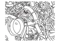
Tighten the flare nut
on fuel tube 2 to the specified torque.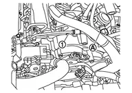
: 15 N·m Tighten the flare nut
on fuel tube 2 to the specified torque.
: 15 N·m Tighten the fuel tube 2
mounting bolt to the specified torque.: 25 N·m Tighten the flare nut
on fuel tube 2 to the specified torque.: 38 N·m Tighten the flare nut
on fuel tube 2 to the specified torque.: 38 N·m
Install removed parts in the reverse order of removal.
Inspection
INSPECTION AFTER INSTALLATION
Fuel Leakage Inspection
Check for fuel leakage according to the following procedure.
Turn ignition switch ON (with engine stopped). With fuel pressure applied to fuel piping, check for fuel leakage at the locations where parts are removed and reinstalled.
Start the engine, increase the engine speed, and check again for fuel leakage at the locations where parts are removed and reinstalled.