Vtc
Exploded View
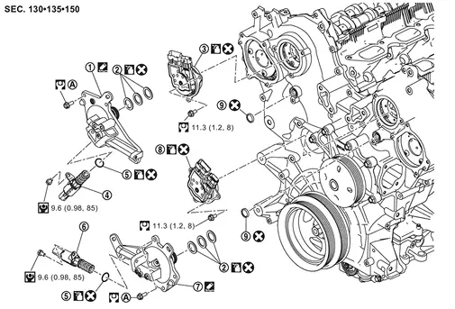
 |
Valve timing control cover (bank 1) |  |
Seal ring |  |
Electric intake valve timing control actuator (bank 1) |
 |
Valve timing oil control solenoid valve (bank 1) |  |
O-ring |  |
Valve timing oil control solenoid valve (bank 2) |
 |
Valve timing control cover (bank 2) |  |
Electric intake valve timing control actuator (bank 2) |  |
Valve timing control cover oil filter |
 |
Comply with the assembly procedurewhen tightening. Refer to Removal & Installation. | ||||
 |
: N·m (kg-m, ft-lb) | ||||
 |
: N·m (kg-m, in-lb) | ||||
 |
: Always replace after every disassembly. | ||||
 |
: Should be lubricated with oil. | ||||
 |
: Sealing point | ||||
Removal & Installation
REMOVAL
Remove valve timing control covers (bank 1 and bank 2) and gasket as follows:Disconnect valve timing oil control solenoid valve (bank 1 and bank 2) harness connector. Loosen valve timing control cover mounting bolts in the order from 4 to 1 as shown in the figure.

|
: Bank 1 |
 |
: Bank 2 |
 |
: Dowel pin hole |
Remove electric intake valve timing control actuator (bank 1 and bank 2) as follows:Disconnect electric intake valve timing control actuator harness connector. Remove mounting bolts for the electric intake valve timing control actuator (bank 1 and bank 2).
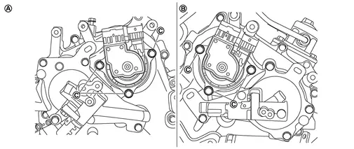
|
: Bank 1 |
|
: Bank 2 |
INSTALLATION
Install valve timing control covers (bank 1 and bank 2) as follows:Install new seal rings in shaft grooves .
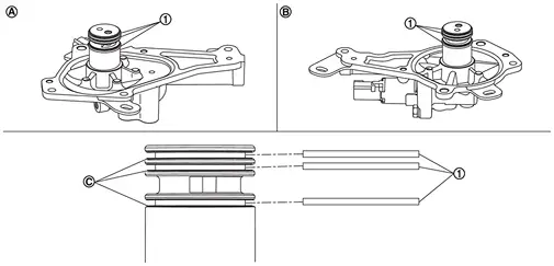
|
: Bank 1 |
|
: Bank 2 |
Apply a liquid gasket (equivalent to ThreeBond 1217H) to the camshaft sprocket cover as shown in the illustration, so that the start and end of the coating overlap.
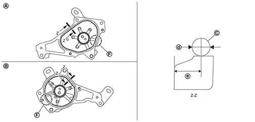
: Bank 1 : Bank 2 : Liquid gasket 
: φ2.7 - 3.7 mm (0.106 - 0.146 in) 
: 4.0 - 5.6 mm (0.157 - 0.220 in) 
: (Overlap) 5.0 mm (0.197 in)
Attaching should be done within 5 minutes after liquid gasket application.
Being careful not to move seal ring from the installation groove, align dowel pins on front cover with holes to install valve timing control covers. Tighten camshaft sprocket cover mounting bolts to the torque specified below in the order from 1 to 4 as shown in the figure. |
: Bank 1 |
|
: Bank 2 |
|
: Dowel pin hole |
|
: 11,3 N·m |
After all bolts are tightened, tighten No. 1 bolt to the specified torque again.
Install electric intake valve timing control actuator.
Align positions of the electric intake valve timing control actuator (bank 1 and bank 2) with the position of the intake camshaft sprocket and install the electric intake valve timing control actuator.