Injection System
GENERAL INFORMATION

Location of Glow Plug System Components
1. Glow plug
2. Coolant temperature sensor
3. Left front wall in driver footwell
4. Glow timer
5. Glow relay
6. Battery
DIESEL ENGINE OPERATING PRINCIPLE In a diesel engine, clean air is drawn into the cylinders and compressed to a very high ratio. As a result, the temperature in the cylinders rises above the ignition temperature of diesel fuel. Diesel fuel ignites on its own, so spark plugs are not required.
On a cold engine, the fuel ignition temperature cannot be reached by compression alone. In this case, the engine must be preheated. For this purpose, each swirl chamber has a glow plug that heats the combustion chamber.
Fuel is drawn directly from the fuel tank by the distributor-type injection pump. The injection pump generates the required high pressure (about 130 bar), which is distributed to the cylinders in the correct firing order. At the same time, the injection pump governor meters the fuel supply according to accelerator pedal position. At a specific moment, diesel fuel is injected through the injectors into the prechamber of the corresponding cylinder. Depending on the shape of the prechamber or swirl chamber, the intake air acquires a swirling motion during compression, which promotes optimal mixing of air and injected fuel.
Before reaching the pump, fuel passes through the fuel filter, where contaminants and water are removed. For this reason, it is especially important to drain water from the filter or replace it according to the maintenance schedule.
The injection pump requires no maintenance. All moving parts of the pump are lubricated by diesel fuel. The pump is driven from the crankshaft by the timing belt, which also drives the camshaft.
Since a diesel engine operates on compression ignition, it cannot be shut off by cutting ignition voltage, and it has a solenoid valve for this purpose. When the ignition switch is turned off, power is removed from the solenoid valve and it closes the fuel supply passage. This ensures that the fuel supply is interrupted before the steering wheel locks when the ignition key is removed. When the engine is started, voltage is supplied through the ignition switch to the solenoid valve, which opens the fuel supply passage.
GLOW PLUG SYSTEM On a cold engine, the fuel ignition temperature cannot be reached by compression alone, so the engine must be preheated. For this purpose, a glow plug is screwed into each combustion chamber. The glow plug consists mainly of a housing and a heating element pressed into it. As soon as voltage is applied, the heating coil in the element heats to 850° C within a few seconds, so the preheating period before starting rarely exceeds 10 seconds. After the glow indicator lamp on the instrument panel goes out, the engine can be started. The preheating duration is controlled by the electronic control unit located in the passenger compartment, next to the glove box on the right. The engine glow control unit receives engine temperature information from the coolant temperature sensor. Based on this information, the control unit determines the duration and value of the glow current.
Glow System Check If starting difficulties occur, first check engine compression. If compression pressure is too low, the engine will not start at low temperatures. If compression is normal, check the operation of all glow plugs.
Test Conditions The battery must be fully charged, with battery voltage of at least 12 V. Engine must be cold (ambient temperature) or engine temperature below +60° C. At higher engine temperature, disconnect the connector from the coolant temperature sensor.
Current Supply Check This check can be performed without removing the glow plugs.
PROCEDURE
1. Connect a voltmeter between the glow plug and ground.
2. Insert the key into the ignition switch and turn on the glow system. After 3 seconds, battery voltage (12 V) should appear; if not, check the ignition switch contacts.
3. Then switch off the ignition and turn on the glow plug preheating. The measuring instrument should show battery voltage (12 V or higher) within 20 seconds. The time depends on the glow plug temperature, battery voltage, coolant temperature, and the position of the ignition/starter switch between ON and OFF.
4. Disconnect terminal S on the starter so that the starter cannot operate.
5. Briefly turn the ignition key to “Start” and hold it in the “Ignition ON” position. The voltmeter should show battery voltage (12 V or higher) within 20 seconds.
6. Reconnect terminal S to the starter.
7. Start the engine and let it run at idle. The voltmeter should show battery voltage (12 V or higher) for 5 minutes, assuming the coolant temperature is below 60 °C.
8. If there is no current supply, have the glow plug control unit inspected at a workshop.
Glow Plug Control Relay Check
PROCEDURE
1. Remove the relay.
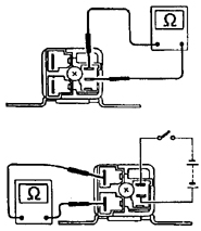
2. Check the relay coil for short circuit with an ohmmeter (0 Ω).
3. Connect the ohmmeter to the relay output. Continuity should be present.
4. Apply battery voltage to the coil terminals. The relay should switch over and the output resistance should be 0 Ω.
5. Otherwise, replace the relay.
Glow Plug Check
PROCEDURE
1. Check the busbar for rust. Clean or replace if necessary.
2. Check the glow plug for visible external damage.
3. Disconnect the connector of the glow plug control unit. Connect the ohmmeter between terminal 5 of the connector and ground. Reading should be 0 Ω, otherwise replace the wire.
4. Unscrew the connection cable and busbar from the glow plug.
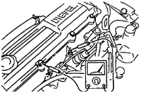
5. Check the resistance with an ohmmeter between the glow plug terminal and the engine block (ground). Reading should be 0 Ω. If an open circuit is detected, replace the glow plug.
6. Check all glow plugs in this way.
Warning The actual resistance of a glow plug is very low and difficult to measure with a standard multimeter. Required value: 0.650 Ω. Clean oil off the glow plug before measuring.
7. Unscrew the faulty glow plug and replace it.
8. Reinstall the connection cable and busbar, first fitting the spring washer and flat washer onto the glow plug.
9. If disconnected, reconnect the coolant temperature sensor connector.
Warning If the fault is not found but the engine starts poorly, inspect the glow plugs while they are heated. To do this, remove the injectors and inspect the glow plugs through the openings. Glow plugs with burnt tips
10. Burnt glow plug tips are mainly caused by faulty injectors.
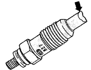
11. If glow plugs of this type (arrow) are found, it is sufficient to replace them only.
12. Check the injectors for injection pressure and leak tightness (to be performed at a workshop).
Coolant Temperature Sensor Check
PROCEDURE
1. Remove the temperature sensor.
2. Connect the ohmmeter to the sensor terminals. Then either cool the sensor with coolant spray or heat it in a water bath to check it.
Specifications Temperature/Resistance –15 °C 11.5 kΩ 0 °C 5.6 kΩ +10 °C 3.7 kΩ +40 °C 1.2 kΩ Ignition Switch Contact Check
PROCEDURE
1. Remove the lower steering column cover.
2. Disconnect the ignition switch connector.
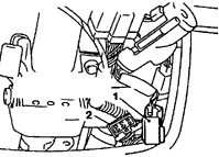
3. Connect the ohmmeter to connector (1) and check the resistance (2 – connector to ignition switch and starter). There should be no continuity.
4. Insert the key into the ignition switch. Resistance should be up to 0 Ω, otherwise replace the ignition switch.
5. Install the lower steering column cover.
Test yourself
A quick Nissan Sunny quiz: every answer comes with an explanation and a link to the manual page.