NE Signal Circuit (C1224). SA1 Solenoid Circuit (C1225-C1228,C1468,C1469,C146A,C146B). Steering Angle Sensor Circuit (C1231)
NE Signal Circuit (C1224)
DESCRIPTION
The skid control ECU (brake actuator assembly) receives engine speed signals from the ECM via CAN communication.
DTC No. | Detection Item | DTC Detection Condition | Trouble Area |
|---|---|---|---|
C1224 |
NE Signal Circuit |
The vehicle speed is 6 km/h or more, the +BS terminal voltage is between 9.6 and 16.5 V, and the engine speed signal is more than 12800 rpm for 2.5 seconds or more. |
|
PROCEDURE
CHECK CAN COMMUNICATION SYSTEM
(a) Check if CAN communication system DTCs are output.
Click here 
Result | Proceed to |
|---|---|
DTCs are not output |
A |
DTCs are output |
B |
| B |  |
INSPECT CAN COMMUNICATION SYSTEM |
|

CHECK SFI SYSTEM
(a) Check if SFI system DTCs are output.
Powertrain > Engine > Trouble CodesResult | Proceed to |
|---|---|
DTCs are not output |
A |
DTCs are output |
B |
| A | |
REPLACE ECM |
| B | |
INSPECT SFI SYSTEM |
SA1 Solenoid Circuit (C1225-C1228,C1468,C1469,C146A,C146B)
DESCRIPTION
These solenoids turn on when signals are received from the skid control ECU (brake actuator assembly) and they control the pressure acting on the wheel cylinders to control the braking force.
DTC No. | Detection Item | DTC Detection Condition | Trouble Area |
|---|---|---|---|
C1225 |
SA1 Solenoid Circuit |
Solenoid valve signal does not match the check result. |
|
C1226 |
SA2 Solenoid Circuit |
Solenoid valve signal does not match the check result. |
|
C1227 |
SA3 Solenoid Circuit |
Solenoid valve signal does not match the check result. |
|
C1228 |
STR Solenoid Circuit |
Solenoid valve signal does not match the check result. |
|
C1468 |
SFR Solenoid Circuit |
Solenoid valve signal does not match the check result. |
|
C1469 |
SFL Solenoid Circuit |
Solenoid valve signal does not match the check result. |
|
C146A |
SRR Solenoid Circuit |
Solenoid valve signal does not match the check result. |
|
C146B |
SRL Solenoid Circuit |
Solenoid valve signal does not match the check result. |
|
WIRING DIAGRAM
Refer to DTC C146E.
Click here 
NOTICE:
When replacing the skid control ECU (brake actuator assembly), perform system variant learning and acceleration sensor zero point calibration.
Click here
PROCEDURE
RECONFIRM DTC
HINT:
These codes are detected when a problem is determined in the skid control ECU (brake actuator assembly).
The solenoid circuits are in the skid control ECU (brake actuator assembly).
Therefore, solenoid circuit inspection and solenoid unit inspection cannot be performed. Be sure to check if any DTCs are output before replacing the skid control ECU (brake actuator assembly).
(a) Clear the DTCs.
Chassis > ABS/VSC/TRAC/EPB > Clear DTCs(b) Turn the engine switch off.
(c) Start the engine.
(d) Drive the vehicle at a speed of 20 km/h or more.
(e) Check if the same DTC is output.
Chassis > ABS/VSC/TRAC/EPB > Trouble CodesResult | Proceed to |
|---|---|
Both C1225, C1226, C1227, C1228, C1468, C1469, C146A and C146B are not output |
A |
C1225, C1226, C1227, C1228, C1468, C1469, C146A or C146B is output |
B |
HINT:
- The skid control ECU (brake actuator assembly) performs self diagnosis of the solenoid circuit after the engine switch is turned on (IG).
- If the normal system code is output (no DTCs are output), slightly jiggle the connectors, wire harness, and fuses of the skid control ECU (brake actuator assembly).
- If any DTCs are output while jiggling a connector or wire harness of the skid control ECU (brake actuator assembly), inspect and repair the connector or wire harness.
- If no DTCs were output when reconfirming DTCs, checking for intermittent problems is necessary because it is suspected that the original DTCs were stored due to the poor connection of a connector terminal.
| A |  |
USE SIMULATION METHOD TO CHECK |
| B | |
REPLACE BRAKE ACTUATOR ASSEMBLY |
Steering Angle Sensor Circuit (C1231)
DESCRIPTION
The skid control ECU (brake actuator assembly) receives steering angle sensor signals via CAN communication. When a malfunction occurs in the communication line with the steering angle sensor, DTC U0126 (Lost Communication With Steering Angle Sensor Module) is stored.
DTC No. | Detection Item | DTC Detection Condition | Trouble Area |
|---|---|---|---|
C1231 |
Steering Angle Sensor Circuit |
While steering angle sensor communication is enabled, a malfunction signal output is received during the sensor self check (sensor malfunction). |
Steering angle sensor internal malfunction |
WIRING DIAGRAM
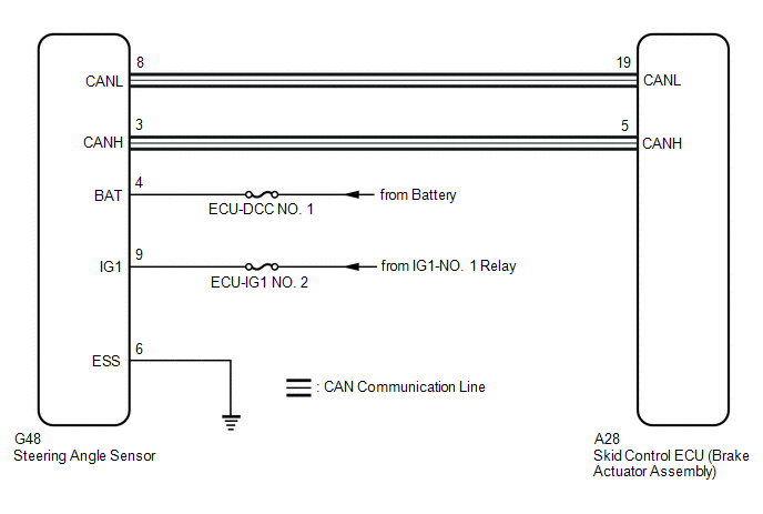
NOTICE:
Inspect the fuses for circuits related to this system before performing the following procedure.
HINT:
- When U0126 is output together with C1231, inspect and repair the trouble areas indicated by U0126 first.
Click here

- When a speed sensor or yaw rate and acceleration sensor (airbag sensor assembly) is malfunctioning, DTCs for the steering angle sensor may be output even when the steering angle sensor is normal. When DTCs for a speed sensor or the yaw rate and acceleration sensor (airbag sensor assembly) are output together with DTCs for the steering angle sensor, inspect and repair the speed sensor and yaw rate and acceleration sensor (airbag sensor assembly) first, and then inspect and repair the steering angle sensor.
PROCEDURE
CHECK DTC
(a) Clear the DTCs.
Chassis > ABS/VSC/TRAC/EPB > Clear DTCs(b) Turn the engine switch off.
(c) Turn the engine switch on (IG) again and check that no CAN communication system DTCs are output.
Click here
(d) Drive the vehicle at a speed of 35 km/h, turn the steering wheel to the right and left, and check that no speed sensor and/or yaw rate and acceleration sensor DTCs are output.
Chassis > ABS/VSC/TRAC/EPB > Trouble CodesResult | Proceed to |
|---|---|
C1231 is output |
A |
CAN communication system DTCs are output |
B |
Speed sensor and/or yaw rate and acceleration sensor DTCs are output |
C |
C1231 is not output |
D |
HINT:
- When CAN communication system DTCs are output, repair the CAN communication system before repairing each corresponding sensor.
- If there is a malfunction in a speed sensor or the yaw rate and acceleration sensor (airbag sensor assembly), an abnormal value may be output even though the steering angle sensor is normal.
- If speed sensor and yaw rate and acceleration sensor DTCs are output simultaneously, repair the sensors and inspect the steering angle sensor.
| B |  |
INSPECT CAN COMMUNICATION SYSTEM |
| C | |
REPAIR CIRCUITS INDICATED BY OUTPUT DTCS |
| D | |
USE SIMULATION METHOD TO CHECK |
|

CHECK HARNESS AND CONNECTOR (POWER SOURCE TERMINAL)
(a) Turn the engine switch off. |
|
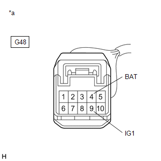
(b) Remove the steering wheel and column cover.
(c) Make sure that there is no looseness at the locking part and the connecting part of the connector.
OK:
The connector is securely connected.
(d) Disconnect the G48 steering angle sensor connector.
(e) Check both the connector case and the terminals for deformation and corrosion.
OK:
No deformation or corrosion.
(f) Measure the voltage according to the value(s) in the table below.
Standard Voltage:
Tester Connection | Condition | Specified Condition |
|---|---|---|
G48-9 (IG1) - Body ground |
Engine switch on (IG) |
11 to 14 V |
G48-4 (BAT) - Body ground |
Always |
11 to 14 V |
| NG | |
REPAIR OR REPLACE HARNESS OR CONNECTOR (POWER SOURCE CIRCUIT) |
|
CHECK HARNESS AND CONNECTOR (GROUND TERMINAL)
(a) Turn the engine switch off. |
|
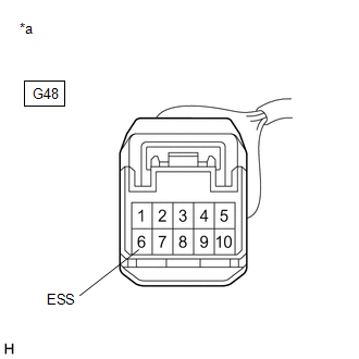
(b) Measure the resistance according to the value(s) in the table below.
NOTICE:
Before measuring the resistance of the steering angle sensor, turn the engine switch off and leave the vehicle for 1 minute or more without operating the key or switches, or opening or closing the doors.
Standard Resistance:
Tester Connection | Condition | Specified Condition |
|---|---|---|
G48-6 (ESS) - Body ground |
1 minute after engine switch off |
Below 1 Ω |
| OK | |
REPLACE STEERING ANGLE SENSOR |
| NG | |
REPAIR OR REPLACE HARNESS OR CONNECTOR (GROUND CIRCUIT) |