Precaution. Problem Symptoms Table. Slip Indicator Light does not Come ON
Precaution
PRECAUTION
PRECAUTION FOR DISCONNECTING CABLE FROM NEGATIVE AUXILIARY BATTERY TERMINAL
NOTICE:
When disconnecting the cable from the negative (-) auxiliary battery terminal, initialize the following system(s) after the cable is reconnected:
System | See Procedure |
|---|---|
Lane Departure Alert System (w/ Steering Control) |
 |
Intelligent Clearance Sonar System |
|
Parking Assist Monitor System |
|
Panoramic View Monitor System |
|
Pre-collision System |
|
Lighting System (for HV Model with Cornering Light) |
TROUBLESHOOTING PRECAUTIONS
(a) When there is a malfunction with terminal contact points or part installation problems, removal and installation of the suspected problem parts may return the system to the normal condition either completely or temporarily.
(b) In order to determine the malfunctioning area, be sure to check the conditions at the time the malfunction occurred, such as DTC output and Freeze Frame Data, and record it before disconnecting each connector or removing and installing parts.
(c) Since the system may be influenced by malfunctions in systems other than the brake control system, be sure to check for DTCs in other systems.
HANDLING PRECAUTIONS
(a) Do not remove or install electronically controlled brake system parts such as the steering angle sensor, yaw rate and acceleration sensor (airbag ECU assembly) or brake pedal stroke sensor assembly except when required, as they need to be adjusted correctly after removal and installation.
(b) Be sure to perform preparation before work and confirmation after work is completed by following the directions in the repair manual when working on the electronically controlled brake system.
(c) When removing/installing or replacing an electronically controlled brake system related component, disconnect the cable from the negative (-) auxiliary battery terminal before performing the procedure.
NOTICE:
After turning the power switch off, waiting time may be required before disconnecting the cable from the negative (-) auxiliary battery terminal. Therefore, make sure to read the disconnecting the cable from the negative (-) auxiliary battery terminal notice before proceeding with work.
Click here
(d) If the skid control ECU (brake booster with master cylinder assembly), brake booster pump assembly, brake actuator assembly or a sensor has been removed and installed, it is necessary to check the system for problems after the parts have been reassembled. Check for DTCs using the Techstream. Also check that the system functions and signals received by the ECU are normal using Test Mode (Signal Check).
HINT:
If a Test Mode (Signal Check) inspection is not performed, a sensor not calibrated malfunction DTC may be stored even if the skid control ECU (brake booster with master cylinder assembly) and all sensors are normal.
(e) If the brake pedal is depressed before the brake control system is prepared to operate, the pedal stroke may seem unusually long or short. This is due to the fact the stroke simulator cut solenoid has not yet operated and is not a malfunction.
After the power switch is turned on (IG) or the brake pedal is depressed twice or more, the stroke simulator will operate and the brake pedal stroke will remain consistent.
DTC PRECAUTION
(a) Warnings for some DTCs cannot be cleared by only repairing the malfunctioning parts. If the warning is displayed even after repair work, the DTC should be cleared after turning the power switch off.
NOTICE:
If a DTC for a malfunctioning part reappears after it is cleared, then it has been stored again.
(b) When 2 or more DTCs are detected, perform circuit inspections one by one until the problem is identified.
CHASSIS DYNAMOMETER PRECAUTION
(a) Enter Inspection Mode to disable TRAC and VSC operation when using a chassis dynamometer.
Refer to Inspection Mode Procedure: Click here
CAUTION:
- Do not use the drum tester with any of the lock chains disconnected.
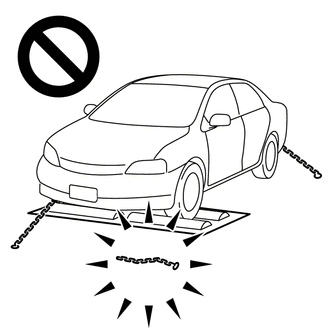
- Using the drum tester with a lock chain disconnected could cause the vehicle to begin moving unexpectedly.
- Do not use the drum tester while the TRAC or VSC is able to operate.
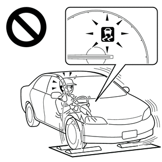
- TRAC or VSC operation could cause the vehicle to begin moving unexpectedly.
DISABLING AND ENABLING OF TRAC AND VSC BY OPERATION OF VSC OFF SWITCH
(a) Switching of mode
Operating the VSC OFF switch switches the system between normal mode, TRAC off mode and VSC off mode.
(1) Normal mode
If the VSC OFF switch is pressed when in TRAC off mode or VSC off mode, the system enters normal mode.
In normal mode, TRAC and VSC are enabled.
The system is set to normal mode when the power switch is turned on (IG).
(2) TRAC off mode
If the VSC OFF switch is pressed when in normal mode, the system enters TRAC off mode. When in TRAC off mode, TRAC is disabled and the multi-information display in the combination meter assembly displays "Traction Control Turned Off".
When the vehicle reaches a certain vehicle speed when in TRAC off mode, the system automatically returns to normal mode.
(3) VSC off mode
When the VSC OFF switch is pressed and held for 3 seconds or more with the vehicle stopped, the system enters VSC off mode. When in VSC off mode, TRAC and VSC are disabled, the multi-information display in the combination meter assembly displays "Traction Control Turned Off" and the VSC OFF indicator light is illuminated.
The system does not automatically return to normal mode based on vehicle speed when in VSC off mode.
CAN COMMUNICATION SYSTEM PRECAUTIONS
(a) The CAN communication system is used for communication between the skid control ECU (brake booster with master cylinder assembly), steering angle sensor, yaw rate and acceleration sensor (airbag ECU assembly) and other ECUs. If there is a malfunction in a CAN communication line, corresponding DTCs for the communication line are output.
(b) If any CAN communication DTCs are output, repair the malfunction, then troubleshoot the VSC system while communication is normal.
(c) In order to enable CAN communication, a specific type of wiring is used for the CAN communication lines. The wiring used for each communication line is a twisted pair of wires that have an equal length. A bypass wire should not be used, because the data being transmitted will be corrupted.
Problem Symptoms Table
PROBLEM SYMPTOMS TABLE
If there are no DTCs but the problem still occurs, check the suspected areas for each problem symptom in the order given in the table below and proceed to the relevant troubleshooting page.
Electronically Controlled Brake SystemSymptom | Suspected Area | Link |
|---|---|---|
ABS warning light abnormal (Remains on) |
Refer to the procedure for "ABS Warning Light Remains ON" |
 |
ABS warning light abnormal (Does not come on) |
Refer to the procedure for "ABS Warning Light does not Come ON" |
|
Brake warning light / red (malfunction) abnormal (Remains on) |
Refer to the procedure for "Brake Warning Light Remains ON" |
|
Brake warning light / red (malfunction) abnormal (Does not come on) |
Refer to the procedure for "Brake Warning Light does not Come ON" |
|
Brake warning light / yellow (minor malfunction) abnormal (Remains on) |
Refer to the procedure for "Brake Control Warning Light Remains ON" |
|
Brake warning light / yellow (minor malfunction) abnormal (Does not come on) |
Refer to the procedure for "Brake Control Warning Light does not Come ON" |
|
Brake hold standby indicator light abnormal |
Refer to the procedure for "Brake Hold Standby Indicator Light Circuit" |
|
Brake hold operated indicator light abnormal |
Refer to the procedure for "Brake Hold Operated Indicator Light Circuit" |
|
Slip indicator light abnormal (Remains on) |
Refer to the procedure for "Slip Indicator Light Remains ON" |
|
Slip indicator light abnormal (Does not come on) |
Refer to the procedure for "Slip Indicator Light does not Come ON" |
|
TRAC does not operate |
Refer to the procedure for "TRAC does not Operate" |
|
Excessive brake pedal travel (No fluid leaks and no air in system) |
Refer to the procedure for "Excessive Brake Pedal Travel (No Fluid Leaks and No Air in System)" |
|
ABS does not operate |
Refer to the procedure for "ABS does not Operate" |
|
ABS operates before necessary when braking |
Refer to the procedure for "ABS Operates Before Necessary When Braking" |
|
VSC does not operate or VSC does not operate correctly |
Refer to the procedure for "VSC does not Operate or VSC does not Operate Correctly" |
|
Abnormal brake pedal response on first depression |
Refer to the procedure for "Abnormal Brake Pedal Response on First Depression" |
|
Brake actuator operation sound is loud during initial check |
Refer to the procedure for "Brake Actuator Operation Sound is Loud during Initial Check" |
|
VSC OFF switch abnormal |
Refer to the procedure for "VSC OFF Switch Circuit" |
|
Meter buzzer abnormal |
Refer to Meter / Gauge system |
|
Abnormal Noise is Heard from the Engine Compartment when Depressing the Brake Pedal |
Refer to the procedure for "Abnormal Noise is Heard from the Engine Compartment when Depressing the Brake Pedal" |
|
Slip Indicator Light does not Come ON
DESCRIPTION
The skid control ECU (brake booster with master cylinder assembly) is connected to the combination meter assembly via CAN communication.
NOTICE:
After replacing the skid control ECU (brake booster with master cylinder assembly), perform linear solenoid valve offset learning, ABS holding solenoid valve learning, yaw rate and acceleration sensor zero point calibration and system information memorization after performing "Reset Memory".
Click here 
PROCEDURE
CHECK CAN COMMUNICATION SYSTEM
(a) Check if CAN communication system DTCs are output.
Click here
Result | Proceed to |
|---|---|
DTCs are not output. |
A |
DTCs are output. |
B |
| B |  |
INSPECT CAN COMMUNICATION SYSTEM |
|

PERFORM ACTIVE TEST USING TECHSTREAM (SLIP INDICATOR LIGHT)
(a) Select the Active Test on the Techstream.
Click here
Tester Display | Measurement Item | Control Range | Diagnostic Note |
|---|---|---|---|
Slip Indicator Light |
Slip indicator light |
Indicator light ON/OFF |
Observe combination meter assembly |
Tester Display | Measurement Item | Range | Normal Condition | Diagnostic Note |
|---|---|---|---|---|
Slip Indicator Light |
Slip indicator light |
ON or OFF |
ON: Indicator light on OFF: Indicator light off |
- |
Slip Indicator Light
Slip Indicator Light
(b) Check the operating condition of the slip indicator light when operating it using the Techstream.
Result | Proceed to |
|---|---|
Slip indicator light in the Data List does not change using the Active Test. |
A |
Slip indicator light in the Data List turns ON/OFF using the Active Test. |
B |
| A | |
REPLACE BRAKE BOOSTER WITH MASTER CYLINDER ASSEMBLY |
|
INSPECT COMBINATION METER ASSEMBLY
(a) Perform the Active Test of the combination meter assembly (meter CPU) using the Techstream.
Click here
Slip Warning
(b) Check that the slip indicator light turns on or off in accordance with the Active Test.
OK:
The slip indicator light turns on or off in accordance with Techstream operation.
| OK | |
REPLACE BRAKE BOOSTER WITH MASTER CYLINDER ASSEMBLY |
| NG | |
INSPECT METER / GAUGE SYSTEM |