Brake Booster(for Gasoline Model)
Components
COMPONENTS
ILLUSTRATION
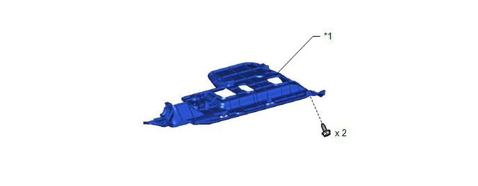
*1 |
NO. 1 INSTRUMENT PANEL UNDER COVER SUB-ASSEMBLY |
- |
- |
ILLUSTRATION
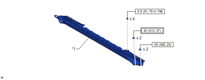
*1 |
FRONT CENTER UPPER SUSPENSION BRACE SUB-ASSEMBLY |
- |
- |
 |
Tightening torque for "Major areas involving basic vehicle performance such as moving/turning/stopping" : N*m (kgf*cm, ft.*lbf) |
 |
N*m (kgf*cm, ft.*lbf): Specified torque |
ILLUSTRATION
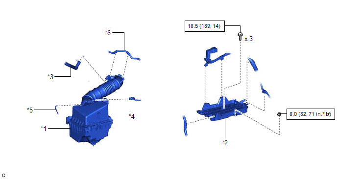
*1 |
AIR CLEANER ASSEMBLY WITH AIR CLEANER HOSE |
*2 |
BATTERY CLAMP SUB-ASSEMBLY |
*3 |
NO. 2 VENTILATION HOSE |
*4 |
MASS AIR FLOW METER SUB-ASSEMBLY CONNECTOR |
*5 |
VACUUM HOSE |
*6 |
NO. 1 FUEL VAPOR FEED HOSE |
|
N*m (kgf*cm, ft.*lbf): Specified torque |
- |
- |
ILLUSTRATION
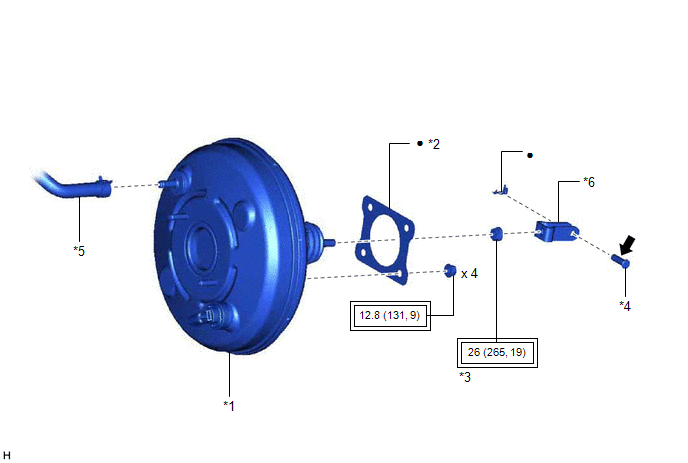
*1 |
BRAKE BOOSTER ASSEMBLY |
*2 |
BRAKE BOOSTER GASKET |
*3 |
LOCK NUT |
*4 |
PUSH ROD PIN |
*5 |
UNION TO CHECK VALVE HOSE |
*6 |
BRAKE MASTER CYLINDER PUSH ROD CLEVIS |
|
Tightening torque for "Major areas involving basic vehicle performance such as moving/turning/stopping" : N*m (kgf*cm, ft.*lbf) |
● |
Non-reusable part |
 |
Lithium soap base glycol grease |
- |
- |
ILLUSTRATION
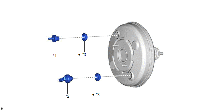
*1 |
BRAKE VACUUM CHECK VALVE ASSEMBLY |
*2 |
VACUUM WARNING SWITCH ASSEMBLY |
*3 |
CHECK VALVE GROMMET |
- |
- |
● |
Non-reusable part |
- |
- |
Disassembly
DISASSEMBLY
PROCEDURE
1. REMOVE BRAKE VACUUM CHECK VALVE ASSEMBLY
(a) Remove the brake vacuum check valve assembly from the brake booster assembly.
(b) Remove the check valve grommet from the brake booster assembly.
2. REMOVE VACUUM WARNING SWITCH ASSEMBLY
(a) Remove the vacuum warning switch assembly from the brake booster assembly.
(b) Remove the check valve grommet from the brake booster assembly.
Inspection
INSPECTION
PROCEDURE
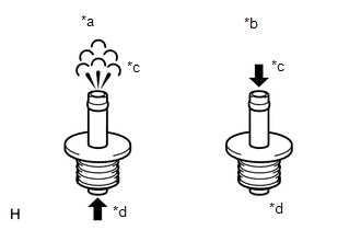
1. INSPECT BRAKE VACUUM CHECK VALVE ASSEMBLY
(a) Check that there is ventilation from the booster side to the engine side, and no ventilation from the engine side to the booster side of the brake vacuum check valve assembly. HINT: If the result is not as specified, replace the brake vacuum check valve assembly. |
|
Installation
INSTALLATION
PROCEDURE
1. INSTALL BRAKE BOOSTER GASKET
(a) Install a new brake booster gasket to the brake booster assembly.
2. INSTALL BRAKE BOOSTER ASSEMBLY
(a) Temporarily install the brake booster assembly to the vehicle body.
NOTICE:
Do not apply excessive force to the brake lines.
(b) Temporarily install the lock nut and brake master cylinder push rod clevis to the brake booster assembly.
NOTICE:
Fully tighten the lock nut when adjusting the brake pedal height.
(c) Install the 4 nuts to secure the brake booster assembly.
Torque:
12,8 N·m {131 kgf·cm, 9 ft·lbf}
(d) Connect the connector to the vacuum warning switch assembly.
3. INSTALL PUSH ROD PIN
Click here 
4. CONNECT UNION TO CHECK VALVE HOSE
(a) Connect the union to check valve hose to the brake booster assembly, and slide the clip to secure it.
5. INSTALL BATTERY CLAMP SUB-ASSEMBLY
(a) Install the battery clamp sub-assembly with the 3 bolts and nut. Torque: Bolt : 18,5 N·m {189 kgf·cm, 14 ft·lbf} Nut : 8 N·m {82 kgf·cm, 71 in·lbf} |
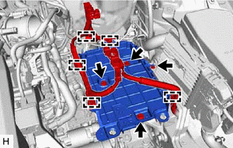 |
(b) Engage the 5 clamps to the battery clamp sub-assembly.
6. INSTALL AIR CLEANER ASSEMBLY WITH AIR CLEANER HOSE
Click here
7. INSTALL FRONT CENTER UPPER SUSPENSION BRACE SUB-ASSEMBLY
Click here
8. INSTALL COWL TOP VENTILATOR LOUVER SUB-ASSEMBLY
Click here
9. INSTALL NO. 1 INSTRUMENT PANEL UNDER COVER SUB-ASSEMBLY
Click here
10. INSTALL BRAKE MASTER CYLINDER SUB-ASSEMBLY
Click here
11. INSPECT AND ADJUST BRAKE PEDAL
Click here
On-vehicle Inspection
ON-VEHICLE INSPECTION
PROCEDURE
1. INSPECT BRAKE BOOSTER ASSEMBLY
(a) Airtightness check
(1) Start the engine and stop it after 1 or 2 minutes. Slowly depress the brake pedal several times. HINT: If the brake pedal can be depressed nearly to the floor the first time, but on the 2nd and 3rd time cannot be depressed as far, the brake booster assembly is airtight. |
|
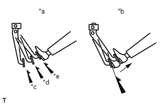
(2) Depress the brake pedal with the engine running, and stop the engine with the brake pedal depressed.
HINT:
If there is no change in the brake pedal reserve distance while holding the brake pedal depressed for 30 seconds, the brake booster assembly is airtight.
(b) Operation check
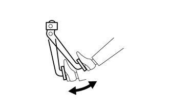
(1) Depress the brake pedal several times with the engine switch off and check that there is no change in the brake pedal reserve distance when the brake pedal is depressed. |
 |
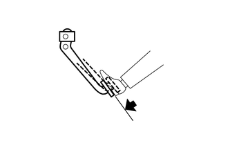
(2) Depress and hold the brake pedal, then start the engine. HINT: If the brake pedal goes down slightly, operation is normal. |
 |
Reassembly
REASSEMBLY
PROCEDURE
1. INSTALL VACUUM WARNING SWITCH ASSEMBLY
(a) Install a new check valve grommet to the brake booster assembly.
(b) Install the vacuum warning switch assembly to the brake booster assembly as shown in the illustration.
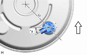
*a |
30° +/- 20° |
 |
Up |
2. INSTALL BRAKE VACUUM CHECK VALVE ASSEMBLY
(a) Install a new check valve grommet to the brake booster assembly.
(b) Install the brake vacuum check valve assembly to the brake booster assembly.
Removal
REMOVAL
The necessary procedures (adjustment, calibration, initialization or registration) that must be performed after parts are removed and installed, or replaced during brake booster assembly removal/installation are shown below.
Necessary Procedures After Parts Removed/Installed/ReplacedReplaced Part or Performed Procedure | Necessary Procedure | Effect/Inoperative Function when Necessary Procedure not Performed | Link |
|---|---|---|---|
| *: When performing learning using the Techstream. Click here |
|||
Battery terminal is disconnected/reconnected |
Perform steering sensor zero point calibration |
Lane departure alert system (w/ Steering Control) |
 |
Pre-collision system |
|||
Intelligent Clearance Sonar System* |
|||
Lighting System (for Gasoline Model with Cornering Light) |
|||
Memorize steering angle neutral point |
Parking assist monitor system |
|
|
Panoramic View Monitor System |
|
||
NOTICE:
Make sure to release vacuum from the brake booster assembly before removing the brake master cylinder sub-assembly from the brake booster assembly.
PROCEDURE
1. PRECAUTION
NOTICE:
After turning the engine switch off, waiting time may be required before disconnecting the cable from the negative (-) battery terminal. Therefore, make sure to read the disconnecting the cable from the negative (-) battery terminal notices before proceeding with work.
Click here
2. REMOVE BRAKE MASTER CYLINDER SUB-ASSEMBLY
Click here
3. REMOVE NO. 1 INSTRUMENT PANEL UNDER COVER SUB-ASSEMBLY
Click here
4. REMOVE COWL TOP VENTILATOR LOUVER SUB-ASSEMBLY
Click here
5. REMOVE FRONT CENTER UPPER SUSPENSION BRACE SUB-ASSEMBLY
Click here
6. REMOVE AIR CLEANER ASSEMBLY WITH AIR CLEANER HOSE
Click here
7. REMOVE BATTERY CLAMP SUB-ASSEMBLY
(a) Disengage the 5 clamps from the battery clamp sub-assembly. |
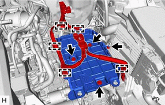 |
(b) Remove the 3 bolts, nut and battery clamp sub-assembly.
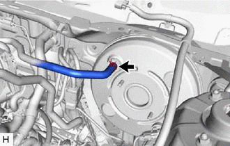
8. DISCONNECT UNION TO CHECK VALVE HOSE
(a) Slide the clip and disconnect the union to check valve hose from the brake booster assembly. |
 |
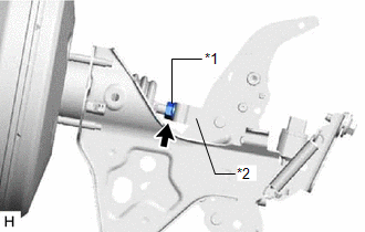
9. LOOSEN LOCK NUT
(a) Loosen the lock nut of the brake master cylinder push rod clevis. |
|
10. REMOVE PUSH ROD PIN
Click here
11. REMOVE BRAKE BOOSTER ASSEMBLY
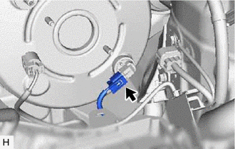
(a) Disconnect the connector from the vacuum warning switch assembly. |
 |
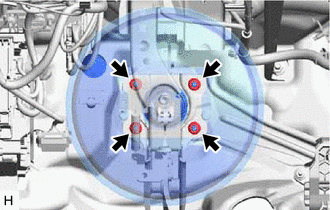
(b) Remove the 4 nuts and push the brake booster assembly toward the engine compartment. NOTICE: Do not apply excessive force to the brake lines. |
 |
(c) Remove the brake master cylinder push rod clevis and lock nut from the brake booster assembly.
(d) Remove the brake booster assembly from the vehicle body.
NOTICE:
Do not apply excessive force to the brake lines.
12. REMOVE BRAKE BOOSTER GASKET